APV Chip Timing Adjustment in DAQ Controllers
180 likes | 204 Views
Explore the structure, functions, and key components of the APV25-S1 chip in DAQ controllers, focusing on adjusting timing settings. Learn about clock values, registers, latency, and modes to optimize data collection and analysis. Discover how to fine-tune ADC clocks and utilize software tools for efficient data processing.

APV Chip Timing Adjustment in DAQ Controllers
E N D
Presentation Transcript
APV Readout Controllers DAQ by Mikko Nykänen
Topic • I try explain mainpoints of reading APV25-S1 chip in DAQ • At begining I tell whole structure of DAQ, parts, main purpose and functions • But main topic is APV chip and how we can adjust the timing in DAQ • In APV we go through components, how much time is spend and what we can change in registers • We also go throught little how we can change APV settings, mainly how mode affects to DAQ
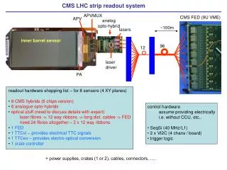
Parts Control computer, with ISA Bus + PCMIO interface ARC Board Power +5V(1.5A) / -5V(0.15A) 2 x FE Adapters 2 x APV25-S1 chips Cables 50 pin, 2x20pin, and 2 APV and power cables ARCS
ARC Board • Rate 20/40MHz • 6 Channels • Resolution 8bit • Memory 8K x 8bit per channel • External (NIM) or Internal trigger (software) • Internal clock 40MHz or External up to 40MHz • Expansion port • Clock, trigger, synchronised trigger and APV trigger
Hybrid I/O • 6 differential voltage -> 6 APVs in one port • 50 Ohms resistance • 3 Standard Buffered I2C • 2 LVDS clock and 2 LVDS trigger lines • Dimensions • 19” crate or Double Euro Format
Trigger&Clock Local crystal oscillator, software/external trigger -> synchronised to system clock Trigger is distributed via link or missing clock pulses Group 1&2 2 groups of 3x8bit FADC For correct sample timing ->tune FADC clock 0-10x1.7ns Data is stored in 8Kbyte RAM in each channel Data lenght ARC – Block diagram
Slow control • 2xI2C controller • LV control • Hydrids powered by FE boards • On/off switch if nessacery • Hybrid currents are monitored by third I2C control
By using address via PCMIO you can read or write data in board or in APV Next colum tells what you can see in address Status register Write DAC/ Read RAM Write memory/soft trigger Write APV trigger data Slow control ADC clock delay Write stop address Write RAM data Address
Software • ARC use LabView program • Userfriedly program and easy to use • But to main point in this prensentation • DAQ • For timing is the ADC clocks value important • In APV register you can also change timing by changing latency • But most important thing in DAQ is what is the mode in APV
APV25 Register • In program you can change preamplifier, sharperer, bias current and few other values • Latency is one of the value here • E.g if you put latency to 132 you get 3.3us delay • Mode • Defines how APV behaves alltogether
Mode selection • Basically you put value to mode and you are happy, not quite • Mode number is based on 6bit number and when you select in table what you want to APV to do we calculate the numerical value
Mode register • This picture is from APV user guide 2.2 • So you select how the measurements are done and then put the to mode
APV25-S1 Analogue pipeline ASIC Idea is to process data prior to sending it APV chip has following parts: preamplifier, sharper, 192 column analogue memory(buffer) When APV collects data to buffer it can keep history of earlier events. In one channel there is data for last 4us period in pipeline. (25ns x192) Sharper and preamplifier use 50ns
Main point in APV is the buffer. Data in there does not over write we make flag that is ready -> timing should be easy • APV is ready to take data around every 5-6us • This makes the chip dead-timeless, so even fast it can collect events quite efficient
Timing • In software you can change two values. • 1. is the latency in APV register(chip) • 2. is the ADC clock, is used to fine tuning DAQ • You should keep mind that when the trigger signal comes the DAQ starts after 70/35 clock pulse around 1.6-0.8us • System clock 40MHz -> 25ns • Delays from cables is not taken account
Times • ADC clock 0-17ns • You can change this on fly and you can seek best position to collect data from screen • Can be changed by moving the lever in ARCS software • APV register: Latency • Here you cant go over value 160 in settings • Input value in APV register, latency • Value 0 to reasonable 132, 0-3.3us delay
Few words • We went through main points • Soon I do better one presentation/ document and there I include more exact data and calculations • Final goal is to make manual, how to build this system and how to use it. • What tests does • How settings affect to results • But programs manual does this also so have to think different approach->to maybe find a way optimace latencys and delays • Give working test setup and good manuam with it