Download
1 / 19
190 likes | 285 Views
Detailed overview of PHOS cooling system status from 1-27 October, including temperature, humidity, interlocks, and control parameters for achieving stabilization. Information on compressors, pumps, valves, sensors, and control units involved in the cooling process outlined. Explanation of the cooling algorithm based on compressor activation and feedback temperature sensing. Role of different servers and programs in monitoring and controlling the cooling system highlighted. Stabilization algorithm parameters and control strategies discussed.

E N D
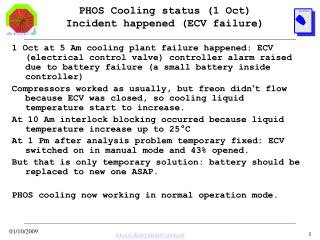
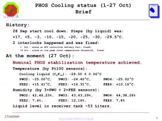
PHOS Cooling status (1-27 Oct)Brief History: 28 Sep start cool down. Steps (by liquid) was: +17, +5, -3, -10, -15, -20, -25, -30, -29.5°C. 2 interlocks happened and was fixed: • 1 Oct – alarm on ECV controller battery fail, fixed; • 19 Oct – alarm on low pump cover temperature threshold, fixed. At the moment (27 Oct): Nominal PHOS stabilization temperature achieved. Temperature (by Pt100 sensors): Cooling liquid (C6F14): -29.50 ± 0.06°C PWO2: -25.00°C, PWO3: -24.40°C, PWO4: -25.02°C FEE2: +15.41°C, FEE3: +16.31°C, FEE4: +10.16°C. Humidity (by 3×PWO + 2×FEE sensors): PWO2: 42,46,23%, PWO3: 43,43,29%, PWO4: 64,38,26% FEE2: 7,4%, FEE3: 12,16%, FEE4: 7,8% Liquid level in receiver tank ~53 Liters.
PHOS Cooling status (1-27 Oct) PHOS temperatures (overview) Nominal stabilization temperature achieved 21 Oct FEE2 FEE3 PWO2 FEE4 PWO4 PWO3 Interlock 1 Oct. cooling liquid (C6F14) Interlock 19 Oct.
PHOS Cooling status (1-27 Oct) PHOS temperatures (details) In constant FEE state ± 0.1°C PWO stability shown PWO3 PWO2 PWO3 temperature 0.5°C higher then PWO2,PWO4 (why?) PWO4 FEE switch on/off cause temperature variations Temperature difference between PWO and cooling liquid is about 4.5°C cooling liquid (C6F14) Stability of cooling liquid average (per control cycle) temperature are: -29.50 ± 0.06°C
PHOS Cooling status (1-27 Oct)Cooling liquid level ~53 L Temperature effect + (possible) leak ~1 L/week (?) Interlock 1 Oct by ECV controller battery, +25°C Interlock 19 Oct by pump cover temperature +5°C -3°C -5°C ~3 Litres of C6F14 filled 21 Oct -10°C Now ~53.3 Litres Need more time to eastimate leak -15°C -20°C -25°C -30°C
PHOS Cooling status (1-27 Oct)Pump cover temperatures Pumps works in round-robin order (8 hours per cycle) to equalize working times Pump2 Pump1
PHOS Cooling status (1-27 Oct)Compressor cover temperatures Comp.2 Comp.3 Comp.4 Comp.1 Compressors also works in round- robin order (8 hours per cycle) to equalize working times
PHOS Cooling System status (1-27 Oct) Concept scheme (just to remind) DCS server alidcscom072 phs_top project PVSS 4 compressors, 2 pumps, 3 heaters, 2 valves, Electric Control Valve + controller, fan, 3 pressure + 14 temperature sensors, liquid level sensor, thermo/oil/pressure relays, funless industrial computer, 10×I-7000 RS-485 remote data acquisition modules, 6×ELMB cards, 15 humidity + 96 temperature sensors in PWO,FEE Cooling server alidcscom252 LAN1 DIM LAN2 RS-485 Water condenser for freon cooling Freon R404A receiver Control unit (ADC, DIO etc) PHOS ECV controller Electric Control Valve Condenser (discharge header) Receiver tank 65L C6F14 Feedback temperature sensor Heat Exchanger R404A C6F14 4 Compressors Evaporator (suction header) 2 Pumps
PHOS Cooling System status (1-27 Oct) PHOS DCS servers scheme PHOS cooling control - alidcscom252 (AliPhosCool program) PHOS cooling client - alidcscom074 (PVSS, phs_col project) PHOS cooling top GUI –alidcscom072 (PVSS, phs_top project)
PHOS Cooling System status (1-27 Oct) Cooling control server: alidcscom252 Cooling plant works as DIM server under control of AliPhosCool program designed in VNIIEF,Sarov. RS-485 and CAN devices uses for data taking & control. Cooling server alidcscom252 Special funless industrial computer, located inside cooling plant
PHOS Cooling System status (1-27 Oct) Cooling top GUI server: alidcscom072 Cooling plant GUI works as DIM client under PVSS. It’s fully integrated into ALICE DCS structures. But (at the moment) shifter can only view cooling data. To control cooling, expert should login to alidcscom252.
PHOS Cooling System status (1-27 Oct) Stabilization algorithm PHOS cooling stabilization algorithm based on compressor switch on/off by feedback temperature sensor. So liquid temperature is not constant, but average temperature per control cycle is stable (±0.1°C).
PHOS Cooling status (1-27 Oct)Stabilization: control parameters • Control parameters: • Tstab – wanted stabilization temperature of cooling liquid • Delta – temperature corridor to switch compressors on/off • NbMin – minimal number of compressors (when T < Tstab-Delta) • NbMax – maximal number of compressors (when T > Tstab+Delta) • Monitor parameters: • Taver – achieved average (per control cycle) temperature of liquid • Caver – achieved period (in minutes) of control cycle • Naver – achieved average (per control cycle) number of compressors Main control parameter is Tstab. Delta, NbMin, NbMax depends on Tstab. Parameters chosen to achieve stable periodic control cycle (when possible). Large Caver “sigma” means control cycle instability (large variations of period) Table shows used parameter values
PHOS Cooling status (1-27 Oct)Stabilization: power problem As shown in table and picture, at -30°C we are working near maximum of compressor’s power (~94% of max. power). This cause some instability of control cycle (see pic.). Remind that we have another (more powerful) cooling machine in b.167. At the moment this machine is not ready for operation, so we should plan this item for the next year. Control cycle period is not stable enough
PHOS Cooling System status (1-27 Oct) Safety: Alarms and Interlocks PHOS cooling plant have 3 outcome Interlocks: • Hardware (normal opened relay) – signal in case of cooling system power off or control computer hang • Software (DIM service) – signal in case of alarms, i.e. dangerous conditions (some parameter out of threshold) • Network (DIM service) – shows that cooling server (alidcscom252) still alive Software alarm produce interlocks by 35 conditions. Interlock mean that cooling plant halted because it could not continue safe operation. Important note: Cooling system alarms protect cooling plant against damage, but not PHOSPWO & FEE. PHOS protection is job for higher DCS level (PVSS, phs_top project).
PHOS Cooling System status (1-27 Oct) Safety: Alarms and Interlocks Software alarms : 35 conditions Each alarm condition have: 1) Flag (enable/disable) 2) Timeout (milliseconds) 3) Threshold (optional parameter) Positive timeout produce temporary device blocking Negative timeout produce Interlock, i.e. fatal alarm and system HALT Interlock require shifter’s command to Reset
PHOS Cooling System status (1-27 Oct) Problems and discussions • Leak ~1 L per week in PHOS-4, ~8 month of work (without liquid filling). More liquid should be purchased next year (~60 liters ?). • Cooling system’s Control Parameters and Alarms tuning should be done after period of test operation (partly done). • It’s not quit clear how L3 magnetic field influent to temperature sensors in PWO. Should be tested. • Phs_top (PVSS) actions on cooling plant interlocks is still under discussion and should be modified (maybe). • Detail documentation (manuals) should be written for “cooling experts”. • For next year new cooling machine (more powerful) should be assembled and connected.