Sub-threshold Sense Amplifier (SA) Compensation Using Auto-zeroing Circuitry
Sub-threshold Sense Amplifier (SA) Compensation Using Auto-zeroing Circuitry. Peter Beshay Department of Electrical Engineering University of Virginia, Charlottesville. 01/21/2014. Outline. Motivation Introduction DAZ Circuit 16kB SRAM Chip Measurements Conclusion. Motivation.

Sub-threshold Sense Amplifier (SA) Compensation Using Auto-zeroing Circuitry
E N D
Presentation Transcript
Sub-threshold Sense Amplifier (SA) Compensation Using Auto-zeroing Circuitry Peter Beshay Department of Electrical Engineering University of Virginia, Charlottesville 01/21/2014
Outline • Motivation • Introduction • DAZ Circuit • 16kB SRAM • Chip Measurements • Conclusion
Motivation Source: IdeaConnection.com Source: groups.csail.edu/ Source: Implantable-device.com
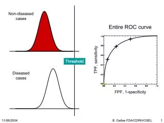
Motivation SRAM are used in implantable devices • Contribute significantly to the total System-on-chip (SOC) power consumption SRAM Power Consumption (1) (1) N. Verma, Phd thesis
Motivation Minimum Energy occurs in sub-threshold [1] Eactive = CVDD2 Etotal/operation minimized in sub-VT Main Limitations Process Variations effect, Slow Speed Normalized Energy VDD (V) Energy Consumption vs. VDD (1) (1) N. Verma, Phd thesis
Motivation Work Focus Minimizing the energy of the read operation of sub-threshold SRAMs. • Sense Amplifier are utilized during the read operation of the SRAMs. • The intrinsic offset voltage of the SAs causes increased read energy and degraded performance of the SRAM read operation [2].
Outline • Introduction • DAZ Circuit • 16kB SRAM • Chip Measurements • Conclusion
Sense Amplifier =1 if =0 Otherwise
SA Offset Voltage =1 if =0 Otherwise =1 if =0 Otherwise
SA Offset Voltage =1 if =0 Otherwise =1 if =0 Otherwise
6T SRAM Read Operation 6T Bitcell 6T Bitcell 6T Bitcell 6T Bitcell 6T Bitcell 6T Bitcell Row Decoder . . . . . . . . . … 6T Bitcell 6T Bitcell 6T Bitcell SAE
6T SRAM Read Operation 6T Bitcell 6T Bitcell 6T Bitcell 6T Bitcell 6T Bitcell 6T Bitcell Row Decoder . . . . . . . . . … 6T Bitcell 6T Bitcell 6T Bitcell SAE
6T SRAM Read Operation 6T Bitcell 6T Bitcell 6T Bitcell 6T Bitcell 6T Bitcell 6T Bitcell Row Decoder . . . . . . . . . … SAE
6T SRAM Read Operation 6T Bitcell 6T Bitcell 6T Bitcell 6T Bitcell 6T Bitcell 6T Bitcell Row Decoder . . . . . . . . . … SAE
6T SRAM Read Operation = BL= 6T Bitcell 6T Bitcell 6T Bitcell 6T Bitcell 6T Bitcell 6T Bitcell Row Decoder . . . . . . . . . … SAE
6T SRAM Read Operation WL = BL= 6T Bitcell 6T Bitcell 6T Bitcell 6T Bitcell 6T Bitcell 6T Bitcell Row Decoder . . . . . . . . . … WL= SAE
6T SRAM Read Operation WL = BL= 6T Bitcell 6T Bitcell 6T Bitcell 6T Bitcell 6T Bitcell 6T Bitcell Row Decoder . . . . . . . . . … WL= 1 0 SAE
6T SRAM Read Operation WL = BL= 6T Bitcell 6T Bitcell 6T Bitcell 6T Bitcell 6T Bitcell 6T Bitcell Row Decoder . . . . . . . . . … WL= 1 0 SAE
6T SRAM Read Operation ∆V > WL = BL= 6T Bitcell 6T Bitcell 6T Bitcell ∆V 6T Bitcell 6T Bitcell 6T Bitcell Row Decoder . . . . . . . . . … WL= 1 0 SAE
6T SRAM Read Operation ∆V > WL = BL= 6T Bitcell 6T Bitcell 6T Bitcell ∆V 6T Bitcell 6T Bitcell 6T Bitcell Row Decoder . . . . . . . . . SAE … WL= 1 0 SAE
6T SRAM Read Operation ∆V > WL = BL= 6T Bitcell 6T Bitcell 6T Bitcell ∆V 6T Bitcell 6T Bitcell 6T Bitcell Row Decoder . . . . . . . . . SAE … WL= 1 0 SAE
6T SRAM Read Operation WL = BL= 6T Bitcell 6T Bitcell 6T Bitcell ∆V 6T Bitcell 6T Bitcell 6T Bitcell Row Decoder . . . . . . . . . SAE … WL= Pre-charge 1 0 SAE
6T SRAM Read Operation WL = BL= 6T Bitcell 6T Bitcell 6T Bitcell ∆V 6T Bitcell 6T Bitcell 6T Bitcell Row Decoder . . . . . . . . . SAE … WL= Pre-charge 1 0 SAE
6T SRAM Read Operation WL = BL= 6T Bitcell 6T Bitcell 6T Bitcell ∆V 6T Bitcell 6T Bitcell 6T Bitcell Row Decoder . . . . . . . . . SAE … WL= Pre-charge 1 0 SAE
PMOS-input Latch SA Enable the SA Sense the input voltage BL M5 M6 M4 M3 Cross coupled inverter to latch the output M2 M1 OUT Precharge the output to VDD
PMOS-input Latch SA BL=0.45V M5 M6 EN M4 M3 OUT, M2 M1 OUT
PMOS-input Latch SA V= BL=0.45V M5 M6 EN M4 M3 OUT, M2 M1 OUT
Offset Voltage BL=0.5 =0.5 ∆mismatch causes the currents to Be different, for zero differential input (BL=) M5 M6 M4 M3 M2 M1 OUT
Digital Auto-zeroing (DAZ) • We propose a digital auto-zeroing (DAZ) scheme inspired by analog amplifier offset correction. • The main advantages of the approach are • Near-zero offset after cancellation. • Suitable for sub-threshold operation due to the repeated offset compensation phase. • Several attempts have been made before to tackle the problem including: • Redundancy[3] • Transistor upsizing [4] • Digitally controlled compensation [5]
Outline • Introduction • DAZ Circuit • 16kB SRAM • Chip Measurements • Conclusion
Auto-zeroing in analog amplifiers • Amplification is done in two phases • Φ1: Sample the offset on a capacitor • Φ2: Subtract the offset from the input signal Dynamic Offset Cancellation (2) (2) K Kang et al, “Dynamic Offset Cancellation Technique” cse.psu.edu/~chip/course/analog/insoo/S04AmpOffset.ppt
DAZ Scheme • Phase1 (ENR1) • A zero differential input is applied to the sense amp. • Phase2 (ENO) • The SA resolves based on its intrinsic offset. =0 =1
DAZ Scheme • Phase3 (ENR2) • The differential input is applied to the sense amp. • Phase4 (ENI) • The SA resolves based on the differential input. =0 =1
DAZ Circuit • DAZ circuit applied to a latch-based sense amp with PMOS inputs • DAZ circuit uses a split-phase clock and charge pump (CP) feedback circuit for repetitive compensation. ENR1 ENR1 ENR2 ENR2 BL ENI ENI M5 M6 MC2 MC1 M4 M3 M2 M1 OUT Charge Pump
DAZ Circuit • Transistors MC1 and MC2 control the drive strength of the right side of the SA. • The CP controls the drive current in both MC1 and MC2 to equalize the strength of the SA right and left sides. ENR1 ENR1 ENR2 ENR2 BL ENI ENI M5 M6 MC2 MC1 M4 M3 M2 M1 OUT Charge Pump
DAZ Circuit ENR1 ENR1 ENR2 ENR2 BL ENI ENI M5 M6 MC2 Cp MC1 M4 M3 Charge Pump M2 M1 ENR2 M11 OUT M13 M9 M10 ENO M12
Phase 1 ER1: A zero differential input is applied to the sense amp. ENR1 ENR1 ENR2 ENR2 BL ENI ENI M5 M6 MC2 Cp MC1 M4 M3 Charge Pump M2 M1 ENR2 M11 OUT M13 M9 M10 ENO M12
Phase 2 ENO: The SA resolves based on its intrinsic offset. ENR1 ENR1 ENR2 ENR2 BL ENI ENI M5 M6 MC2 Cp MC1 M4 M3 Charge Pump M2 M1 ENR2 M11 OUT M13 M9 M10 ENO M12
Phase 3 ER2: The differential input is applied to the sense amp. ENR1 ENR1 ENR2 ENR2 BL ENI ENI ∆v M5 M6 MC2 Cp MC1 M4 M3 Charge Pump M2 M1 ENR2 M11 OUT M13 M9 M10 ENO M12
Phase 4 ENI: The SA resolves based on the differential input. ENR1 ENR1 ENR2 ENR2 BL ENI ENI M5 M6 MC2 Cp MC1 M4 M3 Charge Pump M2 M1 ENR2 M11 OUT M13 M9 M10 ENO M12
Settling Time = 60us Precision • The precision of the scheme depends on the accuracy of setting the voltage on the output capacitor (Cp).
Cp=0.74pF Offset Tuning Cp=0.43pF • Accuracy (offset voltage) vs. settling time trade-off through Cp tuning. Cp=0.24pF Cp=0.14pF Cp=0.13pF
Outline • Introduction • DAZ Circuit • 16kB SRAM • Chip Measurements • Conclusion
16kB SRAM Test-case • A 20mV DAZ SA is used in a 16kB SRAM with 1bank, 512 rows and 256 columns using commercial 45nm technology node [6]. • 10% reduction of the read energy • 24% reduction of the read delay • 45nm technology test chip. • One regular SA array for benchmarking • DAZ SA array with Cp=32fF. • DAZ circuit limits the absolute value of the maximum offset to 50 mV and provided 80% improvement in σ [6]. Chip Measurements
Limitation • Area overhead (major concern in SRAM designs) • 2.5X for 50mV offset compensation • Can be significant for small offsets • Energy overhead of the continuous calibration (split phases, charge pump) • 3.5X the energy of a regular SA • Sensitivity to split phase frequency.
Outline • Introduction • DAZ Circuit • 16kB SRAM • Chip Measurements • Conclusion
Conclusion • We proposed a circuit that is capable of improving sense-amp offset to near zero, which is valuable for sub-threshold operation due to the repeated calibration phase. • Applying the scheme on a 16 kB SRAM in 45nm technology node showed a reduction in the total energy and delay of 10% and 24% respectively. • Measurements from a test chip fabricated in 45 nm technology showed the circuit’s ability to limit the absolute maximum value of the offset voltage to 50 mV using a 32fF output capacitance.
References • B. H. Calhoun et al. "Sub-threshold circuit design with shrinking CMOS devices." ISCAS 2009. • J. Ryan et al. “Minimizing Offset for Latching Voltage-Mode Sense Amplifiers for Sub-threshold Operation” ISQED 2008. • N. Verma et al. “A 256 kb 65 nm 8T Sub-threshold SRAM Employing Sense-Amplifier Redundancy” ISSCC 2008. • L. Pileggi et al. “Mismatch Analysis & Statistical Design” CICC 2008. • M. Bhargava et al. “Low-Overhead, Digital Offset Compensated, SRAM Sense Amplifiers” CICC 2009. • P. Beshay et al. "A Digital Auto-Zeroing Circuit to Reduce Offset in Sub-Threshold Sense Amplifiers." JLPEA 2013