Download
1 / 25
270 likes | 308 Views
Dive into the world of sequential circuits, learning about latches and flip-flops, state transitions, forbidden inputs, clocked latches, edge-triggered flip-flops, setup times, hold times, and solutions to race condition problems.

E N D
EECS 465: Digital Systems Lecture Notes # 7 (A) Introduction to Sequential Circuits (B) Latches and Flip-Flops (C) Counter Design SHANTANU DUTT Department of Electrical and Computer Engineering University of Illinois, Chicago Phone: (312) 355-1314: e-mail: dutt@eecs.uic.edu URL: http://www.eecs.uic.edu/~dutt
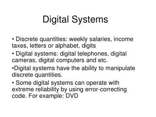
(A) Introduction to Sequential Circuits • Current o/p depends on the current i/p and past history of all i/ps seen by the circuit. Where the relevant past history should be representable by a finite number of classes or states Light = Green O/P = 1 Light = Not red O/P = 0 Reset No Red Red Light State Encode as state = 1 Light = Red O/P = 0 Light = Not green O/P = 0 Encode as state=0 State Transition Diagram Design Problem: Output of the circuit is 1 only if it has seen a red light in the past and currently light is green.
Circuit-Level Model of a Sequential Circuit. x0 I/p from external point Z0 Going to external world Combinational Circuit xn-1 Zm-1 State bits of seq. ckt. yk-1 y’k-1 y0 y’0 Memory Unit Next State Current State
(B) Latches and Flip-Flops Components to store bits ( latches or flip flops ) 1) Problem: can’t store new data 0 1 1 1 Cascade of inverter LD 2) 0 I/P 1/0 O/P LD A Will conduct when A=1, and open when A=0
R Q S Another storage element: NOR gates ( R-S latch ) 3) Cross coupled NOR gates ( R-S latch ) (Reset) Q 0 Q 1 0 R=0 S=1 (Set) B Property of a NOR gate A=0 When one I/P of NOR is 0, it acts like an inverter. When one I/P is 1, then O/P=0. Different I/P conditions for R-S latch: i) R=S=0, current I/P is stored indefinitely ( becomes cascade of inverters) Hold
R=10 Q 0 Oscillates between 1 and 0 when we transit from R=S=1 to R=S=0. 0 01 1 01 S=10 ii) R=1, S=0, when we want to store a 0 in the R-S latch. Q=0, iii) R=0, S=1, when we want to store a 1 in the latch. Q=1, iv) R=1, S=1; Forbidden inputs! Both Q = 0, : Q and its complement have the same value ! Will play havoc in the rest of the logic circuit. Transit to: R=0, S=0. R=1, S=1, both Q and and 0. 0 0 O/P oscillates.
From R, S = 1, 1 transit to R=0, S=1 then Q, transit to 1, 0 ( correctly ) From R, S = 1, 1 transit to R=1, S=0 then Q, correctly transit to 0, 1 R Q R S Q S Q Two implementations for R-S latch: Cross-coupled NOR Cross-coupled NAND Hold State R=S=1 Hold State R=S=0 R=0, S=0 R=1, S=1 Forbidden I/Ps
4) The D-Latch R R1 Q R-S Latch Clocked Latch (level-sensitive clock latch) — see terminology defined later. enb D S1 S D=1, S=1, R=0 Q=1, D=0, S=0, R=1 Q=0, enb=0 R1,S1=0 (hold state) enb=1 enb=1
5) The J-K Latch: — Proposed to get rid of the forbidden I/P problem of R-S i) J=1, K=0: (a) Let Q=1, R=0,S=0 Hold state of R-S Q=1, (b) Let Q=0, , R=0, S=1 Q=1, ii) J=0, K=1 Q=0, using a similar analysis iii) J=K=0 Hold state iv) J=K=1, suppose Q=1, =0 R=1, S=0 Q=0, =1 S=1, R=0 Q=1, =0 This type of toggling continues as long as J=K=1, and the latch is enabled ( CLK=1 below ) 10 10 Q R K R CLK R-S J 1 S Q 01 01
R Q R R R Q Q Q S S S S Q Latch classification with respect to response to “control signal” Terminology: Note that the terminology below applies to all types of latches: R-S, D, J-K, T, etc., though the examples are given for the R-S latch. i) Transparent Latch: O/P responds to latch I/Ps without any enable or clock signal. Symbol: Clock: Fixed frequency alternating 1 and 0 signal ii) Clocked or Level-Sensitive Latch: O/P responds to I/Ps only when enb or clock is at a pre-determined level (high or low — In this example, it is High) R Clock or enb S Symbol: or CLK (low enable) CLK (high enable)
R Q S iii) Edge-Triggered Flip-Flop (FF) or simply Flip-Flop O/P will respond to I/Ps only at either: (a) the positive or rising edge of the enb/clock signal (positive edge-triggered FF), or (b) the negative or falling edge of the enb/clock signal (negative edge-triggered FF). Symbol: R Q S CLK Symbol: CLK Clock: O/P resp. period for a low-enable/clock level sensitive latch O/P response period for a positive edge-triggered FF. O/P response period for a HIGH-enable/clock level-sensitive latch O/P response period for a negative edge-triggered FF
Setup Times and Hold Time of FFs and Latches • Assume, positive edge-triggered D-FF THold relates to propagation delay of another part of circuit. D CLK TSetup relates to propagation delays of various gates in the FF. The high point of the CLK determines the positive edge’s arrival. • If negative edge-triggered TSetup THold D CLK Negative edge arrival • If D-Latch is high-level sensitive: Tsetup and Thold have to be around the negative edge of clock (more specifically, when the clock begins to go low), similar to negative edge-triggered. •If D-Latch is low-level sensitive: Tsetup and Thold have to be around the positive edge of clock, similar to positive edge-triggered.
Solutions to Race Condition Problem with Level Sensitive Latches Solution 1: Master-Slave FF: Q 1 R R-S Latch J R 1 1 1 R-S P 0 Qm 0 Qs K 0 S Q S 0 CLK Slave R-S is level sensitive. Master R-S is level sensitive. Master-Slave J-K is a solution to race-condition problem: Any change in Q, during CLK=0 is not propagated to P, and hence back to Q, during the same CLK=0. Any change to Q, will occur in next CLK=0 period. J Q Master-Slave J-K works similar to a J-K latch: E.g. Let J=1, K=1, CLK=1 Q=1, =0 =1 , P=0 When CLK=0 Q=0, =1 J-K M-S K (O/P responds when CLK goes From 1 to 0)
Assume D=1 D=1=S Q=1, CLK Solution 2: Edge-Triggered FF: D R Holds when clock goes low Q =D Clk=0 R 0 Q S Clk=1 D Q responds to internal S signal; responds to internal R signal. S D 0 Holds D when clock goes low D D When CLK is 1 D I/P is internally sampled but does not appear at the O/P. O/P appears (Q=D) R 0 Q O/P is held (changing D does not cause any change in internal signals in the FF or in its output) Clk=0 S D 0 D
Characteristic Equations of Latches/FFs The next O/P Q+ defined in terms of the current O/P Q and the I/P. (FF/Latch is the simplest possible sequential ckt.) 1) R-S Latch— Truth Table: Values at time t S(t) R(t) Q(t) Q+ = Q( t+ ) 0 0 0 0 0 0 1 1 0 1 0 0 0 1 1 0 1 0 0 1 1 0 1 1 1 1 0 x 1 1 1 x Hold Reset Set Forbidden Q+= S+ Q (Characteristic equation) Q(t)\SR 00 01 11 10 0 0 0 x 1 1 1 0 x 1
Similarly: Characteristic Equations of 2) J-K, Q+ = Q + J. 3) D-FF, Q+ = D 4) Toggle FF/Latch Q+ = T + Q or T-FF / Latch Symbol: Q T Whenever I/P T is high, the FF will toggle, i.e., Q+ = . When T=0, Q+=Q. Of course, these characteristic equations come into play only when the FF/Latch is enabled.
Excitation Table — Reversed Truth Table — What the inputs to FFs should be for given output transitions (Q Q+) Q Q+ R S J K T D 0 0 x 0 0 x 0 0 0 1 0 1 1 x 1 1 1 0 1 0 x 1 1 0 1 1 0 x x 0 0 1
— Conversion between FFs Example: J-K to D J Q D K Logic J Q D CLK K CLK 0 1 Q 0 1 0 D x x 1 This should behave like a D-FF. D D Q O/P function = J J=D Function = K K= x x 1 0 Map the D,Q input combination to a QQ+ transition and then map this to J-K excitation required. Thus, when D=1, Q=0, Q+=1 J,K = 1,x D=0, Q=0, Q+=0 J,K = 0,x D=1, Q=1, Q+=1 J,K = x,0 D=0, Q=1, Q+=0 J,K = x,1. D-FF
Example 2: D J-K should work like a J-K Excitation Table for D J K Q Q+ 0 0 0 0 0 0 1 1 0 1 0 0 0 1 1 0 1 0 0 1 1 0 1 1 1 1 0 1 1 1 1 0 Q Q+ D 0 0 0 0 1 1 1 0 0 1 1 1 Q D J Logic K CLK JK 00 01 11 10 Q TT for J-K 0 0 1 1 0 1 1 0 0 1 Function is J-K FF/Latch Q D Q K J CLK
(C) Counter Design • A counter is a special case of an FSM that cycles through its states on receiving triggering clock pluses. • It does not have any external data I/Ps. 100 No external I/Ps Reset E A Counter O/P 000 011 Logic D Next State bits 001 B C 010 FFs n n CLK • The states need to be encoded by binary bits.
State Transition Diagram and Table for a 3-bit Binary Up-Counter Synthesis (3-Bit Up Counter) Reset Output Next State Toggle Flip-Flop Inputs Input Present State 000 111 001 110 010 101 011 100 C B A C+ B+ A+ TC TB TA 0 0 0 0 0 1 0 0 1 0 0 1 0 1 0 0 1 1 0 1 0 0 1 1 0 0 1 0 1 1 1 0 0 1 1 1 1 0 0 1 0 1 0 0 1 1 0 1 1 1 0 0 1 1 1 1 0 1 1 1 0 0 1 1 1 1 0 0 0 1 1 1 (a) State Transition Diagram (b) State Transition Table (What next state will be given the current state.) FF Excitation Table Revisited Q Q+ R S J K T D 0 0 x 0 0 x 0 0 0 1 0 1 1 x 1 1 1 0 1 0 x 1 1 0 1 1 0 x x 0 0 1 Excitation table for R-S, J-K, T, and D Flip-Flops
From excitation table for FF inputs, get K-map for the FF inputs. CB CB 00 01 11 10 A 00 01 11 10 A 0 0 0 0 0 1 1 0 0 1 0 1 1 1 1 1 1 1 1 1 TC=AB TA=1 CB A 00 01 11 10 K-maps for Up-Counter Using Toggle Flip-Flops. 0 0 0 0 1 1 1 1 0 1 TB=A Obtain logic expr. for FF I/Ps (as functions of current state bits A, B, C, --- A=QA, B=QB, C=QC) and realize the counter
Counters with More Complex Sequencing (Non-Consecutive Binary Outputs) Next State Present State 000 110 010 101 011 C B A C+ B+ A+ 0 0 0 0 1 0 0 0 1 x x x 0 1 0 0 1 1 0 1 1 1 0 1 1 0 0 x x x 1 0 1 1 1 0 1 1 0 0 0 0 1 1 1 x x x State Transition Diagram Implementation Using J-K FFs: State Transition Table Present State Next State Remapped Next State C B A C+ B+ A+ JC KC JB KB JA KA 0 0 0 0 1 0 0 x 1 x 0 x 0 0 1 x x x x x x x x x 0 1 0 0 1 1 0 x x 0 1 x 0 1 1 1 0 1 1 x x 1 x 0 1 0 0 x x x x x x x x x 1 0 1 1 1 0 x 0 1 x x 1 1 1 0 0 0 0 x 1 x 1 0 x 1 1 1 x x x x x x x x x Q Q+ J K 0 0 0 x 0 1 1 x 1 0 x 1 1 1 x 0 J-K Flip-Flop Excitation Table State Transition Table and Remapped Next-State Functions
Next State Functions CB CB 00 01 11 10 A 00 01 11 10 A x x 1 x x x x 0 0 0 0 x x x 1 x x 0 KC JC 1 1 CB CB 00 01 11 10 00 01 11 10 A A 0 1 x x x x x x 1 0 x 0 1 x x 1 x x JB KB 1 1 CB CB 00 01 11 10 00 01 11 10 A A 0 1 0 x x x x x x x x x x 0 x 1 0 0 JA KA 1 1 Remapped K-Maps for J-K Implementation.
J Q CLK K Q J Q CLK K Q J Q CLK K Q Actual Implementation ( Using J-K) + C A B JA A KB C Count signal A B JA KB C J-K Flip-Flop Implementation of 3 Bit Counter.