Download
1 / 10
100 likes | 123 Views
Explore the role of capture solenoids in reducing emittance for particle beams, considering adiabatic tapering effects and pseudo-emittance concepts. Learn about optimizing field strengths for improved beam performance.

E N D
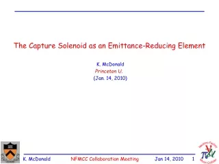
The Capture Solenoid as an Emittance-Reducing Element K. McDonald Princeton U. (Jan. 14, 2010)
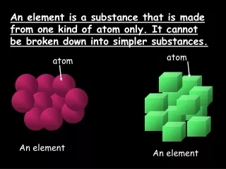
Why Do We Need “Cooling”? Pions are produced at small/zero radius in a thin target, Their initial emittance is nearly zero! When the pions decay to muons their transverse momentum changes by 30 Mev/c, Some increase in transverse emittance, particularly if the pions are well off axis when they decay. But, the major issue is that the RMS emittance = size of phase-space ellipsoid that contains the pions, is large compared to the “true” emittance. We make a great effort to reduce the RMS emittance by “ionization cooling”. In principle, other methods than ionization cooling can be used to shrink the apparent, RMS emittance to a value closer to the true, small emittance. Such methods can be nondissipative. In particular, magnetic fields alone can be used to decrease the apparent, RMS emittance (although this will not decrease the small, true emittance). The production of pions in a strong magnetic field that later “tapers” down to 2 T in the decay and cooling channels can and does serve to reduce the apparent emittance. However, the Collaboration has not made a systematic effort to optimize this process.
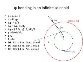
The Adiabatic Invariant of a Helical Orbit If a particle is produced with transverse momentum p0 inside a solenoid of magnetic field strength B0, then its trajectory is a helix of radius R0 = c p0 / e B0 (in Gaussian units). If the particle is produced close to the axis of the solenoid, then its maximum radius with respect to the magnetic axis is 2R0 . The magnetic flux through this helix is 0 = R02 B0 = c2 p02 / e2 B0 1 / B0 for a given transverse momentum. If the solenoidal magnetic field is varied “slowly” with position, the motion of the particle has an “adiabatic invariant”, r p 0 , where r = radius of helix (and not the radial coordinate of the particle with respect to the magnetic axis. Pseudo-Emittance Thus, use of a higher capture field implies a lower invariant quantity r p, which has the dimensions of a transverse emittance. But, r p is not THE transverse emittance (and a magnetic field alone cannot reduce the true transverse emittance). However, the quantity r p is a kind of “pseudo-emittance” of practical relevance to the design of the magnetic transport system, such that a high field B0 in the capture solenoid reduces the “pseudo-emittance” of the system.
Effect of Adiabatic Tapering of the Capture Field If No Pion Decay If the field is reduced slowly from B0 in the capture solenoid to B in the decay/cooling channel, and the pions didn’t decay, the helical trajectory inside the cooling channel obeys e r2 B / c = r p = R0 p0 = c2 p02 / e2 B0 . If the system is designed to accept particles up to a given p0, then the radius and magnetic field of the decay/cooling channel obey r2 B 1 / B0 (recalling that r = 2 R). Hence, use of a larger field B0in the capture solenoid permits reduction of either r or B (or both) in the decay/cooling channel ( cost savings, and increased technical feasibility). Effect of Pion Decay When pions decay to muons, , the muons have 30 MeV/c momentum in the rest frame of the pion. [ p* = E* = (m2 - m2) / 2 m ], and 110 MeV energy [ E* = m - E* ]. Roughly speaking, the transverse momentum of the muon just after its creation by pion decay can differ from the pion’s transverse momentum by 30 MeV/c in any transverse direction. In the worst cases, the helix of the muon extends out to larger distance from the magnetic axis than that of the parent pion, and so the radius of the decay/cooling channel must be larger to maintain good acceptance. As noted by Bob Palmer, this effect is mitigated if the pions decay in a region of stronger magnetic field, since the adiabatic invariant can also be expressed as p2 / B = p02 / B0 . This suggests that we should consider operating the decay channel at a magnetic field intermediate between that of the capture solenoid and the cooling channel (whose field could well be lower than that considered in Study 2 if the capture solenoid field is higher).
Outlook • Use of a higher capture field, followed by a better optimized decay channel, could improve our muon beams 4 ways: • Increased /p ratio. • Lower RMS emittance at the entrance to the cooling channel. • Lower magnetic field in the cooling channel. • Smaller radius for the cooling channel. • One can choose to back off on some of these parameters to obtain even better performance in the others. • Opportunity for rather extensive simulations. Work on this is just beginning.
Recent Studies (D. Neuffer, Jan. 14, 2010) • From Juan G.’s studies • 8-GeV, 20-T beam from H. Kirk • Also 8-GeV, 30-T beam • New H. Kirk initial beam • 20-T, 8-GeV beam, Hg target • from more recent MARS15 • (subtract 2.9 ns to get mean of 0) • more π/8-GeV p (~10%) • Tried 30-T initial beam • “taper” of 20 to 1.5 T scaled to 30 to 2.25 or 1.5T • ~ 20 to 25% more than with 20T
Appendix: A Geometry for a Rotating Solid Target for a Neutrino Factory K. McDonald, Princeton U. (Nov 3, 2009) • Total length of W target, A + B, should be so long that unspent proton beam hitting the magnet has flux comparable to that of the secondary pions. • If need, say, N = 200 targets on the rotating wheel (axis parallel to the magnetic axis) to limit the radiation damage, then • Proton beam coaxial with target, and both tilted so the proton beam does not hit downstream beam window. • Target should be in magnetic field for good capture, but the field can be weak, say 0.5 T. • Taper magnetic field from 0.5 T to nominal 1.75 T of pion transport solenoid. • Rotating target can be upstream of first magnet • Low field long period for pion helices reabsorption a minor issue. • Target diameter can perhaps be larger than 2 cm • Serious flaw: For a pion transport channel of given B and r, the longitudinal-transverse momentum exchange due to the adiabatic invariant r p implies that p/p0 = (B/B0)1/2strongly favors use of B0 much larger (not smaller) than B for maximal capture of pions.
Rotating Target Wheel Should Have an Air Bearing CNGS rotating target failed due to radiation damage to lubrication of the bearings. Use an air bearing for the rotating target wheel.