Download

1 / 9
90 likes | 200 Views
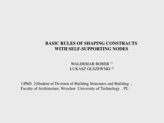
STATIC EFFORT OF SPACE GRIDS WALDEMAR BOBER PhD, adiunkt at the Division of Building Structures and Building, Faculty of Architecture, Wrocław University of Technology, PL. BRYŁY PODSTAWOWE STRUKTURY:. B {D-O}A. FORMA ŁUKOWA STRUKTURY:. B {D-O}A. MODELE BADAWCZE.

E N D
STATIC EFFORT OF SPACE GRIDS WALDEMAR BOBER PhD, adiunkt at the Division of Building Structures and Building, Faculty ofArchitecture, Wrocław University of Technology, PL
BRYŁY PODSTAWOWE STRUKTURY: B {D-O}A
FORMA ŁUKOWA STRUKTURY: B {D-O}A
MODELE BADAWCZE WARIANTY PODPARCIA : P1 – podparcie w węzłach narożnych ( 4 szt.) P2 – podparcie w węzłach narożnych i w dwóch węzłach na środku każdej krawędzi (12 szt.) P3 – podparcie w co drugim węźle obwodowym ( 20 szt.) P4 – podparcie w każdym węźle obwodowym ( 36 szt.) P5 – podparcie w każdym węźle na krawędziach prostych (20 szt.) WARIANTYZAKRZYWIENIA : W 1 1 f = 3,76 m s = 71,0 m W 2 2 f = 7,52 m s = 69,53 m W 3 3 f = 11,28 m s = 67,58 m W 4 4 f = 15,04 m s = 65,23 m W 5 5 f = 18,80 m s = 62,52 m „ f ”oznacza strzałkę łukukołowego, „ s ” rozpiętość struktury
WYNIKI ANALIZY STATYCZNEJ (PODPARCIE) a b c SIŁY W GÓRNEJ WARSTWIE STRUKTURY PODPARTEJ WEDŁUG SCHEMATU : a/ P1 – w węzłach narożnych ( 4 szt.) b/ P3 – w co drugim węźle ( 20 szt.) c/ P5 – na krawędziach prostych (20 szt.)
WYNIKI ANALIZY STATYCZNEJ (WYGIĘCIE) a b c SIŁY W GÓRNEJ WARSTWIE STRUKTURY ZAKRZYWIONEJ WEDŁUG SCHEMATU : a/ W 1 1 f = 3,76 m s = 71,0 m b/ W 3 3 f = 11,28 m s = 67,58 m c/W 5 5 f = 18,80 m s = 62,52 mP4 – podparcie w każdym węźle obwodowym ( 36 szt.)
WYNIKI ANALIZY STATYCZNEJ (CIĄGŁOŚĆ WARSTWY ŚRODKOWEJ) SIŁY W WARSTWIE ŚRODKOWEJ STRUKTURY ZAKRZYWIONEJ WEDŁUG SCHEMATU : W 3 3 f = 11,28 m s = 67,58 m P5 – podparcie w każdym węźle na krawędziach prostych (20 szt.)
WYNIKI ANALIZY STATYCZNEJ (WARTOŚCI EKSTREMALNE) Ekstremalne siły i przemieszczenia przy strzałce łuku f1 = 3,76 m (W1), dla schematu podparcia P1 – P5
WSKAŹNIKI WYTĘŻENIASTATYCZNEGO Ogólny Wskaźnik Wytężenia Statycznego OWWS dla schematów podparcia P1 – P5 OWWS przy strzałkach łuku kołowego f1- f5