Download
1 / 40
410 likes | 732 Views
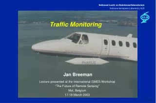
Design of a Sensor Board for an Acoustic Traffic Monitoring System. Gina Colangelo Tufts University Masters’ Project 12/02/2008. Project Goal. To enable the study of a new technique for traffic monitoring using an acoustic array sensor network by:

E N D
Design of a Sensor Board for an Acoustic Traffic Monitoring System Gina Colangelo Tufts University Masters’ Project 12/02/2008
Project Goal To enable the study of a new technique for traffic monitoring using an acoustic array sensor network by: • defining the system architecture of the sensor array board • deriving the system specifications of the sensor array board • designing a PCB for the sensor array board and the interface to the wireless link
Presentation Outline • Introduction to Traffic Surveillance Networks • Background on Passive Acoustic Sensors • System Architecture • System Specifications • Part Selection • Schematic Capture • PCB Layout • Future Goals
Technologies used for Rural Traffic Surveillance • National Survey conducted in 2004 by ITS1 found: • 26 states use Inductive Loop Detectors (ILD) • 21 states use Radar Detectors • 11 states use Video Image Detectors (VIDS) • 5 states use Acoustic Detectors • Vehicle info collected by the sensor networks include: • Traffic Volume • Vehicle Speed • Vehicle Classification • Travel Time • Incident Occurrence 1 ITS or Intelligent Transportation System is a division of RITA which is part of the U.S. Department of Transportation (DOT).
Inductive Loop Detectors (ILD) • How it works: • 1 or more loops of wire are embedded under the road & connected to a control box. • When a vehicle passes over or rests on the loop, inductance is reduced showing a vehicle is present. • Benefits • Established Technology • Not impacted by environmental conditions • Accurate in detecting vehicle presence • Performs well in both high and low volume traffic • Disadvantages • High Cost (up to $10k for initial costs) • Invasive Installation • Potential poor reliability due to improper installation • Not viable for certain locations and road conditions • Unable to directly measure speed or direction
Video Image Detection (VIDS) • Employs machine vision technology to automatically analyze traffic data collected w/ Closed Circuit Television Systems (CCTV) • Benefits: • Rapid Incident detection • Wide area detection capabilities (multi-lane, multi-direction) • Vehicle classification • Estimates traffic queues and speed • Installation does not require lane closures • Can be integrated with other sensor networks • Disadvantages: • High Cost (initial cost > $50k) • Higher Power than other sensor networks • Light conditions can affect surveillance
Radar-based Roadside Sensor • How it works: • Transmits radar pulses • A portion of the energy is reflected or scattered from the vehicle and roadway back toward the sensor • This energy is received and interpreted. • Benefits • Low Power • Most accurate technology for detecting speed • Traffic Count accuracy • Easy installation • Low cost • Disadvantages • Accuracy can be affected by weather conditions (hail, snow, rain) • Directional Detection is poor • Interference could occur with other RF devices
Passive Acoustic Sensors • Passive Road-side Sensor that receives sound waves from passing vehicles. • Benefits: • Low Power • Low Cost • Easy to Install • Directional and Multi-lane Detection • Accurately measures traffic count • Disadvantages: • Accuracy affected by environment factors • Speed measurements are not as accurate as other methods
Summary of Traffic Surveillance Technologies Employed Today: Code: A – Excellent; B – Fair; C- Poor; D – Nonexistent; U – Unknown • Radar and Acoustic sensors are the least expensive to deploy and are the lowest power. • VIDS collect the most information and the data processing possibilties are endless. • Acoustic sensors are the least accurate, but the technology is relatively new. • Acoustic sensors for traffic monitoring has room for improvement: • Improve accuracy • Ability to detect idle traffic • Intelligently process data (Vehicle Classification, Incident Detection)
Acoustic Array Sensor • Research has shown that using arrays of acoustic sensors narrows the detection zone for improved SNR & better accuracy • For this project the following configuration will be evaluated: • 4 microphone arrays per sensor: • 2 arrays form a pair parallel to the road • 2 arrays for a pair orthogonal to the road • Each array contains 12 microphones • Sensors to be deployed road-side about 10m above the road.
Sensor Network System Details • Sound detected by each element in a single array will be summed together and amplified. • 4 analog outputs will be digitized separately and processed. • Processed signals will be transmitted to a gateway node within the wireless sensor network.
Signal Processing: Parallel Pair • A vehicle moves across the detection zone (D2 to D1): • As a vehicle approaches, sound reaches D2 earlier than D1. The time delta will be negative (τ<0). • When a vehicle is at the center of the detection zone, τ=0. • As a vehicle exits the detection zone, τ will be positive. • The rate of change or slope across the detection zone corresponds to the vehicle speed. • To extract the time delay from the actual signals, the cross correlation of D1 and D2 is calculated:
Signal Processing: Orthogonal Pair • A vehicle moves across the detection zone: • As the vehicle approaches, sound will reach D1 earlier than D2. The time difference will be positive and increasing (τ<0). • When the vehicle is at the center of the detection zone, τ will peak. • As the vehicle exits the detection zone, τ will be positive and decreasing. • The sound map for vehicles in lanes closer to the sensor (smaller y) will have smaller peaks than those in lanes further from sensor.
System Architecture • 2 Boards to form complete system: • Sensor Board • Microphone Arrays • Summing Stage • Amplification Stage • System Board • Analog-to-Digital Converter • Processor • RF Transceiver (ISM band of 2.4GHz) • eZ430-RF2480 Demo Kit from TI chosen for System Board • USB-based wireless demo tool • MSP430F2274 Mixed-Signal Microcontroller • CC2480 2.4GHz ZigBee network processor • 2.4GHz Antenna
Sensor Board Architecture • For initial prototype, 1 sensor board per array to allow for array spacing experimentation • Majority of System Gain implemented on Sensor board to maximize SNR. • Clipping Circuit and Anti-Aliasing Filter may be needed to condition signal for ADC.
System Board Architecture • MSP430 Mixed-Signal Microcontroller • AUX Op-Amps can provide extra gain if needed • On-chip 10-bit ADC can multiplex in 4 analog channels for digitizing • CPU can be programmed to compute cross-correlation functions • CC2480 – ZigBee Processor to transmit data to gateway node to main control center over 2.4GHz ISM band
Determining Sensor Board Specs • Power Supply Requirements • Maximum Voltage Output Swing • Element Spacing • Summing Stage Configuration • System Gain • Anti-Aliasing Filter
Power Supply Requirements • 2 Specifications need to be determined: • Supply Voltages • Maximum Current • Sensor Board needs to be portable solution • Low power • Battery operated • Reuse Battery Board included with eZ430-RF2480 Demo Kit: • 2 AAA Batteries in series: 3V supply • Capacity of AAAs: 900-1155mA/h
Maximum Voltage Output Swing • Needs to be limited to Input Range of ADC. • Depending of ADC front-end architecture, over voltage on inputs can cause conversion errors and in some cases damage the ADC. • 10-bit ADC integrated on the MSP430 will be used. • ADC input range is programmable from Vcc to Vss. • For this project, ADC will be programmed to accept an input range of 3V to 0V. • No Clipping Circuit needed on Sensor Board • Amplifiers on Sensor board will not produce a voltage higher than its supply voltage • ADC on the MSP430 clips any signals greater than the programmable upper input range limit. • Benefits from using the same power source solution!
Element Spacing • Spacing b/t array elements will be chosen to achieve the desired detection angle. • Desired Detection Angle: • Sensor board mounted 10m above road (z=10m) • Desired detection zone is 2.5m in any direction at road level. • Detection Angle can be calculated:
Experiment to Determine Element Spacing • Several 3x4 element arrays bread-boarded w/ summing stage: • Array 1: 1.75cm x 1.75cm • Array 2: 2cm x 2cm • Array 3: 2.5cm x 2.5cm • Detection Angle measured by moving a 4kHz sound source across the array from a fixed distance. • Vpk-pk measured at summer output with Oscilloscope
Summing Stage Configuration • Original Design used 1 op-amp to sum all 12 elements • New Design sums the elements in 2 stages: • First stage sums the 3 rows of 4 elements separately • Second stage sums the 3 outputs of the 1st stage • New Design allows for more gain without large R • Improved Rise/Fall Times (τ = RC) • Increased Bandwidth – less Gain per stage (f3dB = GBW/Gain)
Determining System Gain • Experiments conducted to estimate the amount system gain required in the real traffic monitoring environment. • Microphone array prototype board is not portable, and output cannot be stored. • A portable digital sound recorder was used to collect field samples: • 2 Omni-Directional Electret Condenser Microphones • Mic positions can be configured from 45º to 135º (90º was chosen) • 7 Pre-Amp Levels • Recorded sound clips saved as *.WAV
System Gain Experiment • Step 1 – Calibrate the digital recorder to the microphone array in a controlled environment with same sound source for each Pre-Amp Level. • Measured in Lab w/ 4kHz sound source • Array and Recorder in same location for the measurement • Step 2 – Collect Field Data for each applicable Pre-Amp level • 5-10s traffic samples were recorded from a height of 25-30ft from the road • Average of 5 vehicles passed the recorder during each sound clip including motorcycles, small cars, and SUVs. • Step 3 – Download and process *.WAV files to determine peak sound levels • MATLAB code was written to analyze these files • The start and end of each file was removed to eliminate interference • The 2 microphone outputs were summed • The max peak and rms levels were calculated. • Step 4 – Relate the peak sound levels from digital recorder back to the microphone array and determine the required system gain.
System Gain Results Array Output = 100mVpk-pk PreAmp Level 3 optimal in field To calculate Vpk-pk at the array output the following formulas were used: 1. 2. 3. Digital Recorder Peak and RMS Levels from 4kHz Signal in Lab vs. Pre-Amp Level Digital Recorder Peak and RMS Levels from Traffic Sound Clips Calculating the Sound Source Ratio Total System Gain Needed = 4 x 3.5 = 14 Estimated Array Output Vpk-pk and Recommended Gain Settings
Anti-Aliasing Filter • Anti-aliasing filter should be placed before ADC • Prevents harmonics, spurs and broadband noise outside of Nyquist from aliasing back in-band • Improper filtering leads to a decrease in SNR, a reduced dynamic range and an increase in unwanted spurs. • ADC input bandwidth/channel: • clock range: 450kHz - 1.5MHz • Nyquist BW: 225 – 750kHz • 4 chs muxed, BW per ch = 56.25 – 187.5kHz • Frequencies of Interest < 10kHz • Filter Design • Low-pass Butterworth – flat pass- & stop-band • F3dB = 20kHz for flatter phase in pass-band • 1st order provides ~20dB attenuation at FADC/2. • Since microphones have a frequency roll-off response, 1st order should be adequate.
Schematic - Circuit Design • Architecture is finalized • Active Components have been selected: • Analog Devices AD8544 Quad Rail-to-Rail OpAmp • Single Supply Operation: 2.7V to 5.5V • GBWP ~ 1MHz • Low supply current 45uA/amplifier • Emkay MD9745APZ-F Omni-Directional Microphone • Operating Voltage: 2.0V to 10.0V • Frequency Range: 100Hz to 10kHz • S/N Ratio: > 55dB • Altium Designer 6 software chosen for PCB Schematic and Layout
PCB Layout • 4 Layer Board • 2 Signal Layers • GND and Power layer • Board Size is 4’’ by 2.5’’ • All symbol footprints are either finalized or common footprints
Prototype Results (Breadboard) • Current Dissipation • 2.6mA from single 3V supply (original design 15mA from 5V, +9V, and -9V supplies) • Sensor board can operate for approx 400hrs before recharging • Frequency Response: • Op-Amp 1: f3dB= GBWP/Gain = 1MHz/3 = 333kHz • Op-Amp 2: f3dB = 1MHz/5 = 200kHz • Microphone: f3dB = 10kHz • LPF: f3dB = 20kHz Note: Using 1 stage summer, f3dB=1MHz/15 = 66kHz
Future Work • Fabricate, Assemble, and Test Sensor Board PCB • Interface Sensor board with Main system board • Configure ADC on MSP430 • Write code to perform cross-correlation and store results • Perform experiments on Array Spacing • Collect Field Data with this Portable prototype
References • Chen, Shiping, Ziping Sun, and Bryan Bridge. “Traffic Monitoring Using Digital Sound Field Mapping.” IEEE Transactions on Vehicular Technology 50.6 (2001): 1582-1589. • Intelligent Transportation Systems. 2008. http://www.itsdeployment.its.dot.gov/ • ITS Decision, Project of the California Center for Innovative Transportation at UCal Berkeley. 2007. http://www.calccit.org/itsdecision/
Acknowledgements • Yuping Dong • PhD Student conducting research in this area • Professor Chang • Project Advisor • Tufts Wireless Lab