Understanding Torsional Stress in Shafts: Concepts and Examples
This tutorial focuses on analyzing common problems related to torsional stress in shafts, particularly in inclined planes. It covers fundamental concepts of stress in inclined sections and explores the behavior of circular shafts subjected to torsion. With practical examples, the tutorial walks through determining maximum shearing stress, analyzing rotations at different ends of the shaft, and applying relevant equations. Join us during office hours for any inquiries or further clarification on these topics.


Understanding Torsional Stress in Shafts: Concepts and Examples
E N D
Presentation Transcript
Tutorial 6 MECH 101 Liang Tengfei tfliang@ust.hk Office phone : 2358-8811 Mobile : 6497-0191 Office hour : 14:00-15:00 Fri
Outline • Common problems in HW #3 • Stress in an inclined plane • Torsi0nal shaft
Stress in an inclined plane Determine the stress acting on inclined section. Where the area of cross section is 1mm2, the angle is 30o. P=500N
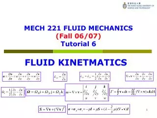
Basic concepts about torsional loading of shafts One important assumption: when a circular shaft, whether solid or tubular, is subjected to torsion, each cross section remains plane and simply rotates about the axis of the member.
Torsional Shaft for uniform shaft,
Example 1 • A shaft shown below is attached to a wall at its left end and is in equilibrium when subjected to the two torques. The shear modulus is 12,000 ksi. Determine • The maximum shearing stress in the shaft. • The rotation of end B of the 6-in segment with respect to end A • The rotation of end C of the 4-in segment with respect to end B • The rotation of end C with respect to end A.
Solution FBD at B FBD at A From the above analysis, we can obtain a torque diagram which represents the torque distribution in the shaft.
Solution (a) Maximum shearing stress What is JAB and JBC ? We have known
Solution (b) The rotation of end B of the 6-in segment with respect to end A Apply the equation for rotation (c) The rotation of end C of the 4-in segment with respect to end B Similarly (d) The rotation of end C with respect to end A