Download
1 / 54
540 likes | 655 Views
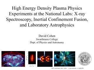
High Energy Density Plasma Physics Experiments at the National Labs: X-ray Spectroscopy, Inertial Confinement Fusion, and Laboratory Astrophysics. David Cohen Swarthmore College Dept. of Physics and Astronomy. astro.swarthmore.edu/~cohen presentations vanderbilt. Talk Outline

E N D
High Energy Density Plasma Physics Experiments at the National Labs: X-ray Spectroscopy, Inertial Confinement Fusion, and Laboratory Astrophysics David Cohen Swarthmore College Dept. of Physics and Astronomy astro.swarthmore.edu/~cohen presentations vanderbilt
Talk Outline Facilities and capabilities Inertial Confinement Fusion (ICF) OMEGA experiments: X-ray spectral diagnostics of ICF materials Laboratory astrophysics Creating an X-ray photoionized nebula in the laboratory
High Energy Density Plasma Physics at National Facilities • Lasers • NOVA (Livermore) - closed in late 1990s - 10 beams, 20 kJ UV light in ~1 ns • OMEGA (U. Rochester/LLE) - opened in 1970s - 60 beams, 30 kJ, UV (Nd glass laser) • National Ignition Facility (NIF) (Livermore) - coming on line this decade - 192 beams, 2 MJ • Z-pinches • Z-machine/PBFA-II (Sandia) - originally built in 1970s - 20 MA of current in a cylindrical wire array - ~2 MJ of X-rays in ~10 ns
These facilities are open to non-lab scientists DOE’s National Laser Users Facilities (NLUF) program enables university scientists access of OMEGA (and previously NOVA), as well as other facilities at Los Alamos, etc. - some coordination with lab scientists and technicians is required/provided Use of the Z-Machine generally requires a Sandia collaborator, but DOE’s fusion grants program (SBSS) provides support and can facilitate collaborations
Types of experiments: generally involving high energy density plasmas (>105 atm) • Can achieve multi-GPa pressures, 103 g cm-3 densities, multi-million K temperatures in 10 cm3 volume • Sophisticated diagnostics are available at these facilities (time resolved imaging and spectroscopy, neutron and other particle detectors, fast radiography, etc.) • Plasma instability studies (instability growth rate, including applications to supernova explosions) • - EOS studies (e.g. of hydrogen under very high pressure, applications to giant planet interiors) • - Radiation and thermal energy transport • - Atomic physics and opacities • - Shock physics
Laser Facilities Generally Nd glass lasers (but 5 kJ gas (KrF) laser at NRL); 1.06 mm IR light, frequency tripled into the near UV; multi-beam (for symmetry and flexibility)
Livermore’s NIF will be completed in several years, and is already operational. Here are some views of the huge target chamber, during its construction.
Lasers can be used directly to accelerate e.g. foils, drive shock waves, and compress material samples Also, they can be used indirectly to generate X-rays - laser light is thermalized by a high-Z foil or inside a high-Z enclosure, or hohlraum
Z-Pinches A current passing through a vaporized wire or other cylindrical plasma generates a poloidal magnetic field that interacts with the current, generating a Lorentz force in the direction of the current axis - the result is a self-pinched plasma (e.g. lightning) - and the on-axis compression can generate a shock wave, that efficiently converts the magnetic energy to heat, and then X-rays. wires B-field Z-axis; net current; foam E x B force
The Z-Machine at Sandia - application of a pulsed-power generator (Particle Beam Fusion Accelerator (PBFA)) - world’s larges Z-pinch and most powerful X-ray source (2 MJ in 10 ns 200 TW of X-ray power) Experimental packages can be fielded near or even within the pinch - hohlraums adjacent to the pinch; capsules and other material samples embedded in the foam core
Talk Outline Facilities and capabilities Inertial Confinement Fusion (ICF) OMEGA experiments: X-ray spectral diagnostics of ICF materials Laboratory astrophysics Creating an X-ray photoionized nebula in the laboratory
Inertial Confinement Fusion (ICF) Deuterium-Tritium fusion reactions have the biggest cross section Energy is released primarily in the form of fast neutrons; there are various schemes for harnessing this energy A working test-reactor is decades off still, but fusion power is an attractive long-term solution to our energy needs • the final products of a fusion reaction weigh 0.7% less than the initial ingredients, thus 0.7% mc2 is converted into energy: One gram of fuel yields 175,000 kW-hours of energy
Different Fusion Methods Practical problem: combination of high temperatures and densities are required to force positively charged nuclei together, but the resulting high pressure will tend to blow fusion plasma (hot ionized gas) apart 3 primary plasma confinement methods I. Gravitational confinement: astrophysical contexts II. Magnetic confinement: tokomaks III. Inertial confinement - inertia of the fuel confines it for the nanoseconds (10-9 s) required for the fusion reaction to proceed
How Does Inertial Confinement Fusion (ICF) Work? A spherical capsule filled with hydrogen fuel is bombarded with energy, compressing and heating a small region in the center of the fuel. The fusion reactions from this central “hot spot” deposit enough energy in the rest of the fuel that fusion occurs there too–this process is referred to as ignition. Note that during the very short period of ignition (a few nanoseconds, or a billionth of a second) the fuel is pushed inward, so its own inertia acts to impede its disassembly; hence the term inertial confinement fusion.
Physical Requirements for fusion – overcoming the Coulomb Barrier Note: center of the Sun has T~15 X 106 K, r ~100 g cm-3 In an ablation-driven capsule implosion with a shock velocity of 300 km s-1, a hot spot with an areal mass of >0.1 g cm-2 and a temperature of several keV can ignite (alpha particle energy deposition exceeds losses). Taken from Lindl, Physics of Plasmas, 2, 3933, 1995.
Indirect-Drive ICF Indirect-drive ICF delivers the energy of a laser (or ion beam) not directly to the fuel capsule, but rather to an enclosure, or hohlraum, in which it is thermalized. This thermal radiation is typically characterized by temperatures of 2 to 3 million K, so it is primarily X-rays. Images of a gold hohlraum used at the NOVA laser at Livermore (far left). The picture on the right was taken in X-rays and shows the laser hotspots on the interior of the hohlraum radiating through the hohlraum walls.
Indirect-drive ICF Capsule Implosion: compression and heating via ablation The X-rays that fill the hohlraum bathe the fuel capsule at its center, depositing energy on the outside of the capule and heating the outer capsule layers (referred to as the ablator). This hot plasma rushes away from the capsule into the relative vacuum of the hohlraum. Conservation of momentum causes compression of the interior of the capsule (the rocket effect), with an inward moving shockwave converging on the fuel in the capsule’s center. radiation wave A hydrodynamical simulation of the ablation and compression of a solid plastic sample by thermal X-rays. The X-rays are incident from the left. Hot, tenuous material expands rapidly off the (previously) solid surface toward the left, while a shockwave moving toward the right compresses the remaining material. shock wave
Clearly, controlling the interaction of the X-rays with the outer ablator layer of the fuel capsule is crucial for generating an efficient implosion and subsequent ignition of the fusion fuel. Typically, fuel capsules consist of a spherical plastic shell (the ablator) surrounding high density hydrogen ice (see the schematic on the left).
Ablator dopants affect the opacity and density, changing the manner in which energy is absorbed by the ablator. By adding mid-Z dopants (like bromine, copper, or germanium) to the plastic or beryllium capsule ablator, we can control the density and opacity of the ablator. This in turn controls the ablation/compression physics in the fuel capsule. The dopants also provide a ‘shield’ against radiation preheat of the fuel, allowing for efficient compression at the lowest entropy possible.
Talk Outline Facilities and capabilities Inertial Confinement Fusion (ICF) OMEGA experiments: X-ray spectral diagnostics of ICF materials Laboratory astrophysics Creating an X-ray photoionized nebula in the laboratory
OMEGA experiments: X-ray spectral diagnostics of ICF materials • Goal: To study the effects of ablator dopants on the radiation-hydrodynamics of the ablation and capsule implosion; and • To develop a technique for diagnosing the instantaneous properties at a location in the interior of a solid sample. • Specifically, we want to measure the time at which the radiation wave reaches a specific depth in the ablator as a function of dopant level.
By putting a planar sample of plastic ablator material on the side of a hohlraum we can simplify the geometry These experiments were carried out in April 2000 at the OMEGA laser. On the right is a photograph of a hohlraum target, on the left is a schematic. Note: these hohlraums, with lasers entering on only one side are referred to as halfraums.
The ablator “packages” are thin, planar sandwiches of actual ablator material surrounding a very thin layer of a spectroscopic tracer ~5 m ~20 m This package, mounted over a hole on the outside of the hohlraum, actually sees a time-dependent radiation field (the “drive”) that is very similar to what’s seen by a spheric capsule in the center of a hohlraum. halfraum radiation NaCl tracer < 0.5 m When we see the spectroscopic signature of the chlorine in the tracer, we know the radiation wave has reached it. Ge-doped or undoped plastic
Experimental Set-up Including schematics of diagnostic lines-of-sight Diagnostics The DANTE camera monitors the time-dependent radiation field inside the halfraum (looking in through the laser entrance hole). The spectrometer looks for Ka absorption signals from the chlorine tracer in the ablator package. Note: only one (blue) beam into the halfraum is shown here,for simplicity. All shots were carried out with 15 beams.
Experimental Configuration LEH facing P-7 (LXS in P-6) Gold Halfraums: L=1200m, R=800m washer/aperture positioning wires Pb-doped plastic mount Bi/Pb backligher foil stalk TVS-X view
Witness plates were mounted on the ends of halfraums; backlighter foils hung ~1.5mm from LEH TVS-Y view TVS-X view of plain foil
Modeling Viewfactor modeling of hohlraum drive, constrained by DANTE (and using measured beam profiles as input) Hydrodynamic calculations for time-dependent witness plate properties (1-D Lagrangian; DCA and UTA atomic and EOS models; short characteristics multi-group radiation transport) CRE post-processing for spectral synthesis We use codes written by Joe MacFarlane at Prism Computational Sciences as well as some publicly available codes written at the U. Wisconsin Fusion Technology Institute.
VisRad Viewfactor Modeling • 15 cone 2 and cone 3 beams into the halfraum • 1 ns square pulse • 3 beams onto the backlighter foil; also 1 ns square, but staggered in time for more even backlighter source. Note: not all beams are shown.
Constraining the viewfactor modeling • Beam powers and pointings are known • Temperature dependent albedo is modeled (separately) • X-ray conversion efficiency (of lasers) is a free parameter Radiation flux monitored on element at DANTE position
Once the hohlraum radiation field is modeled: Hydro simulations of the ablator sample Electron Temperature Note: in Ge-doped sample, the peaks are narrower -- shock wave and radiation wave move slower
Same simulations: Radiation Temperature Slower radiation wave velocity in the doped sample
Spectral synthesis: post-processing of hydro results (undoped sample) Note: Shouldn’t see Be-like until ~0.6 ns. Data are acquired with a fast streak camera and spectrograph
Finally - the data Undoped Doped with 1.5 % Germanium In these figures we’re focusing in on the times when the tracer signals turn on. There’s a delay of between 100 and 200 ps in the appearance of Ka absorption signals on the doped and undoped sides. Note that you can also see the ionization balance moving toward higher stages (Be Li He) as time goes on.
Calculated tracer turn-on time vs. drive temperature red=doped; blue=undoped tracer depth from data
Quick Look at Main Result Shot #26: undoped Shot #28: doped • Some absorption signal, apparently, on a noisy continuum: • Turns on later in the doped sample (and tracer was even shallower in this sample); See progression through ionization states. • But--in both cases--earlier turn-on than models predict
CONCLUSIONS Backlit-absorption spectroscopy of a small sample in an environment containing strong radiation and hot plasma is difficult In both types of targets, the signal turn-on time was earlier (by factor ~2) than expected, and lower ionization stages were not seen). But, signal turned on sooner in undoped sample than in doped sample.
Talk Outline Facilities and capabilities Inertial Confinement Fusion (ICF) OMEGA experiments: X-ray spectral diagnostics of ICF materials Laboratory astrophysics Creating an X-ray photoionized nebula in the laboratory
Laboratory Astrophysics • Astrophysics is traditionally not an experimental science, but materials and processes that are relevant to astrophysics can be produced and studied in the lab: • Hydrodynamics and shock physics • EOS • Materials - dust; PAHs • Atomic physics and radiation transport • Magnetic reconnection • >> Code validation • But problem of scale: trade-offs among density, size, column density/optical depth
Talk Outline Facilities and capabilities Inertial Confinement Fusion (ICF) OMEGA experiments: X-ray spectral diagnostics of ICF materials Laboratory astrophysics Creating an X-ray photoionized nebula in the laboratory
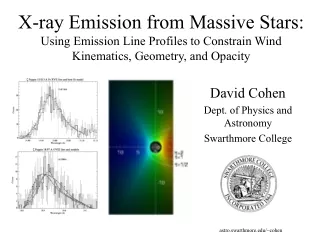
Creating an X-ray photoionized nebula in the laboratory Accretion onto compact objects leads to photoionization-dominated X-ray spectra The circumstellar gas near the source of hard x-rays is highly ionized--overionized for its temperature compared to coronal equilibrium--and produces an x-ray spectrum dominated by radiative recombination continua and recombination cascades. A new generation of X-ray telescopes (Chandra pictured here) is producing high-resolution X-ray spectra for the first time. Artist’s conception of an accretion-powered X-ray binary.
The conditions in the plasma in proximity to the compact object are traditionally described by the ionization parameter (flux/density), which is a measure of the dominance of radiation processes over collisional processes. Contours of constant ionization parameter (logarithmic, in cgs units) are shown for the HMXRB Vela X-1 (above, right; Figure from Sako et al. Ap.J., 525, 921 (1999)).
Motivation With the advent of high-resolution (l/Dl ~ 1000) x-ray spectroscopy in the last several years, a wealth of spectroscopic data for photoionized sources has been generated, and the level of detail and accuracy demanded of models has increased dramatically. By producing and measuring a well-characterized x-ray photoionized plasma in the laboratory, we hope to benchmark the codes used to model x-ray spectra of active galactic nuclei, x-ray binaries, and other astrophysical sources for which photoionization dominates collisional ionization.
Plasmas dominated by collisions and those dominated by photoionization have very different spectra Calculation of iron emission spectrum for a photoionized plasma (left) and a collisional plasma (right). Though the ionization distribution is the same in both models, the spectra are quite different (and the photoionized plasma is much colder). (Figure taken from Liedahl et al. Ap.J., 350, L37 (1990).)
The experimental package consists of a cm-scale neon-filled cell with mylar windows, mounted several cm from the Z-machine’s current return can, inside of which is the pinch itself. Ultimately, we plan on making simultaneous, time-resolved absorption and emission spectroscopic measurements of the gas cell, which can be filled with a variety of gases, including mixtures. The absorption spectroscopy uses the pinch itself as a backlighter. Experiments already completed have used 30 Torr neon (nion ~ 1018 cm-3) observed in absorption with a time-integrated spectrometer.
Viewfactor simulations of the pinch and target are used to calculate the incident spectrum on the gas cell, and also to investigate the spatial uniformity of the irradiance on the cell. gas cell
Hydro simulations of the gas cell Temperature (left) and density (right) at four different times in the simulation of our experiments. The radiation is incident from the left. The initial neon gas density is 1018 cm-3. Note the shock waves launched from the mylar walls at late times. Note also the radiation wave (as evidenced by the temperature gradient) traversing the gas at t=100 ns.
Backlit absorption spectrum (time integrated) A section of our raw data (above). Note the very high principle quantum number lines of He-like neon.