Download
1 / 7
70 likes | 180 Views
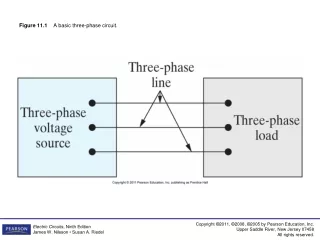
Learn about single-stage integrated circuit amplifiers, MOSFET current sources, and current-steering circuits. Explore common-source and common-gate amplifiers with detailed small-signal analysis and circuit diagrams. Discover impedance transformation properties in CG configuration.

E N D
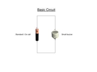
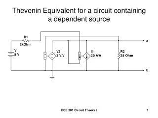
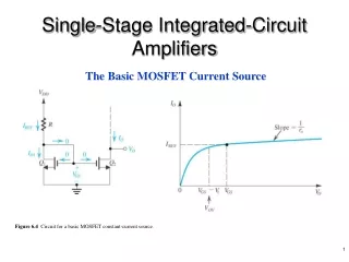
Single-Stage Integrated-Circuit Amplifiers The Basic MOSFET Current Source Figure 6.4 Circuit for a basic MOSFET constant-current source.
MOS Current-Steering Circuits Figure 6.7 A current-steering circuit.
The Common-Source Amplifier Figure 6.17 (a) Active-loaded common-source amplifier. (b) Small-signal analysis of the amplifier in (a), performed both directly on the circuit diagram and using the small-signal model explicitly.
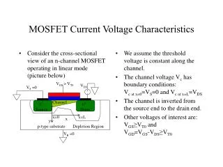
Figure 6.18 The CMOS common-source amplifier; (a) circuit; (b)i–v characteristic of the active-load Q2; (c) graphical construction to determine the transfer characteristic; and (d) transfer characteristic.
The Common-Gate Amplifier Figure 6.27 (a) Active-loaded common-gate amplifier. (b) MOSFET equivalent circuit for the CG case in which the body and gate terminals are connected to ground. (c) Small-signal analysis performed directly on the circuit diagram with the T model of (b) used implicitly. (d) Operation with the output open-circuited.
Figure 6.28 (a) The output resistance Ro is found by setting vi5 0. (b) The output resistance Rout is obtained by setting vsig5 0.
Figure 6.29 The impedance transformation property of the CG configuration.