Download
1 / 38
390 likes | 523 Views
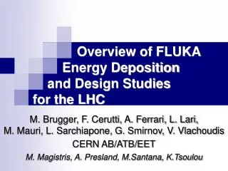
Overview of FLUKA Energy Deposition and Design Studies for the LHC. M. Brugger, F. Cerutti, A. Ferrari, L. Lari, M. Mauri, L. Sarchiapone, G. Smirnov, V. Vlachoudis CERN AB/ATB/EET M. Magistris, A. Presland, M.Santana, K.Tsoulou. Overview.

E N D
Overview of FLUKA Energy Deposition and Design Studies for the LHC M. Brugger, F. Cerutti, A. Ferrari, L. Lari, M. Mauri, L. Sarchiapone, G. Smirnov, V. VlachoudisCERN AB/ATB/EET M. Magistris, A. Presland, M.Santana, K.Tsoulou
Overview • What accelerator problems can be addressed with FLUKA • Critical Quantities to be calculated • Heating/Cooling (ANSYS) • Quench protection • Dose to components • … • Simulation Approach • Generic calculations • Benchmarks if needed/available • Detailed simulations • Interfaces with codes • Related Uncertainties • Needed Details • Clear definition of scenarios/configuration to be studied • Impact parameters, loss maps, magnetic fields,.. • Required quantities and associated limits • Loss assumptions (results scale accordingly) • Applications Workshop on Materials for Collimators and Beam Absorbers
Multifold Structure Workshop on Materials for Collimators and Beam Absorbers
C C Cu Generic Study - Material Selection Different Cases • Graphite + 100mm Copper coating • 1cm Graphite plate on Copper • Block Materials Single Module Prefire Total: 8 bunches Range: 5s – 10s (s=200mm) Proton/Bunch: 1.051011 pr Total: 91011 pr Workshop on Materials for Collimators and Beam Absorbers
New Simulation Strategy • Dynamic FLUKA input generation with several ad-hoc scripts • Detailed description of more than 20 prototypes located in a virtual parking zone • Prototypes are replicated, rotated and translated according to the layout • Magnetic field maps: Analytic + 2D Interpolated • Dynamic generation of the DS and ARC (curved section) • Optics test: Tracking up to 5 sreproduce the correct beta function • Fluka Input (.inp) • LATTICE definitions • Curved Tunnel creation • Magnetic Fields Intensity • Scoring cards • Input Files • FLUKA input template • Twiss files • Object summary • Prototype Info Scripts lattice,… • Fluka Executable • LATTICE transformations • Dynamic adjustment of collimator gaps • Fortran Files • Source routine • Si Damage 1 MeV n eq. • Magnetic Field • History Tracking,… Workshop on Materials for Collimators and Beam Absorbers
Cleaning Insertions Momentum Betatron IR7 Collimation Simulation • Allowed loss rates: • 100 kW continuously • 500 kW for 10s (1% of beam) • 1 MW for 1 s • Quench limits: • Quadrupoles~1 mW/cm3 • Bending~5 mW/cm3 • Geometry Modeling • 1.5 km tunnel • Warm section (straight) • 2 Dispersion suppressors (arc) • >200 objects fully detailed • ~50 Collimators with variable • positioning of the jaws • tilt changed runtime Workshop on Materials for Collimators and Beam Absorbers
Automatic Geometry Creation 1. Initial input file template 2. Space Allocation & Geometry Creation 3. Lattice generation 4. Magnetic Fields mapping Workshop on Materials for Collimators and Beam Absorbers
Geometry of Dipoles Tesla 14m long objects with a field of 8.3 Tesla: 5mrad bend ~3cm sagitta The superconducting dipoles (MB) are made out of 4 straight sections to accommodate the trajectory Workshop on Materials for Collimators and Beam Absorbers
Magnetic Field Example MQW – Warm Quadrupole 2D Interpolated Analytic XY Symmetry Workshop on Materials for Collimators and Beam Absorbers
Primary Inelastic collisions map • Generated by the tracking code • 3 general loss scenarios: Vertical, Horizontal and Skew • At injection at 450 GeV, as well as for 7 TeV low-beta beam • FLUKA source: force inelastic interactions on the previously recorded positions Beam Loss Map For better visualization only, current results show higher contribution for the TCPs Workshop on Materials for Collimators and Beam Absorbers
Reality is a Very Complex Issue ???FirstSurprises ??? !!! Collimators Only !!! !!! Phase-I Only !!! ???FirstOperation ??? Workshop on Materials for Collimators and Beam Absorbers
LHC/IR7 Application Examples • Primary material choice (generic studies) • heating studies assuming adiabatic conditions • Geometry, extended details, verification of tracking, source definition • Collimators – energy deposition studies • Jaws, RF fingers, cooling system • Followed-up by ANSYS calculations (TT40 Beam tests) • Active absorbers to reduce the energy deposition in the cold magnets (DS, ARC) • Passive absorbers to protect the warm magnets • Accident scenarios, commissioning scenarios • BLM detector design (cross-talk, thresholds) • Dose to electronics (UJs, RRs) -> shielding design • LHC Dump, injection protection (Window, CDQ, TCDS,… ) • Phase-II design (SLAC & future) • Scraper studies Workshop on Materials for Collimators and Beam Absorbers
Secondary Collimator Example W • Accurate geometrical representation of the actual collimator design • Different particle loss scenarios • Adopting respective jaw openings • Detailed power load for each component • 3D energy deposition maps for all collimators • Detailed ANSYS studies (see Alessandro’s talk) Workshop on Materials for Collimators and Beam Absorbers
Active Absorber Layout Optimization Quench limit: 1-10 mW/cm3 close to theexpected limit Maximum power deposition in super-conducting coils: ~300 mW/cm3 ~10.0 mW/cm3 ~3 mW/cm3 ~2 mW/cm3 No absorbers 3 absorber 4 absorber 5 absorber Workshop on Materials for Collimators and Beam Absorbers
Phase II Studies – SLAC Design • New detailed FLUKA implementation Stub shaft Aluminum Support post DOWNBEAM SST Support post UPBEAM SST Jaw transition Aluminum Workshop on Materials for Collimators and Beam Absorbers
Sect. FF Sect. EE Sect. BB Sect. DD Sect. CC Sect. AA 90o 0o Y Y Y Y Y Y 126.9o 141.1o142.5 143.5o141.6 X X X X X X Z Z Z Z Z Z TCSM A5L7 TCSM B5L7 TCP C6L7 TCSM A6L7 TCP B6L7 TCP D6L7 A E B D F C X Z Y C F D B E A Phase II Studies – SLAC Design • Fully integrated in the complex layout • Applied to design studies 40.7o42.7 TCSG TCSG Beam 1 Workshop on Materials for Collimators and Beam Absorbers
Phase II Studies – SLAC Design ~ 78 [W/cm3] ~ 76 [W/cm3] Lower left jaw Lowerleft jaw ~ 74 [W/cm3] ~ 60 [W/cm3] Upper right jaw Upper right jaw z ~ 16 [cm] z ~ 18 [cm] z ~ 18 [cm] z ~ 19 [cm] • Latest design changes • Energy density peak cross-checked with former simulations based on a more simplified layout • Detailed heating study possible Lower left jaw ~ 28 [W/cm3] ~ 22 [W/cm3] Upper right jaw z ~ 17 [cm] z ~ 18 [cm] Workshop on Materials for Collimators and Beam Absorbers
A More Detailed Example Passive Absorber Design Workshop on Materials for Collimators and Beam Absorbers
Separation Dipoles: MBW Magnets • ~5 MGy/year, 10 years operation possible, but not guaranteed • 4 spare magnets • In case of repair need coil exchange rather straight forward • Operating temperature ~50-55˚C (T-interlocks trip at 65˚C) • Maximum acceptable temperature increase 10˚K (steady state): MBW=15 kW M. Karppinen Workshop on Materials for Collimators and Beam Absorbers
Technical Drawing Separation Dipoles: MBW Magnets FLUKA Implementation Workshop on Materials for Collimators and Beam Absorbers
Quadrupoles: MQW Magnets • Even 1 MGy/year, -> 10 years might be critical • 4 Spare magnets (however, 3 out of them need repair!) • 1 Set of spare coils, BUT Coil exchange not at all easy • Operating temperature ~50-55˚C (T-interlocks trip at 65˚C • Stored heat is ~60 MJ, thus ~14 kW over 10 s could be enough to trip the T-interlock, if close to outlets • Maximum acceptable temperature increase 10 K (steady state): MQW=10 kW • Injected coil shims likely to fail, thus first leading to coil movements and insulation damage M. Karppinen Workshop on Materials for Collimators and Beam Absorbers
Quadrupoles: MQW Magnets Technical Drawing FLUKA Implementation Workshop on Materials for Collimators and Beam Absorbers
Design Evolution • Evolving IR7 Layout • 60cm long primary collimators • Separation of D3, additional passive absorber (TCAPB) • Various loss scenarios • Technical layout and integration • simple concept (simple block, no cooling) • first ideas (close aperture, cooling is needed) • more sophisticated (sandwich structure) • technically possible (Swiss cheese, but sufficient) • Constraints, limitations, loss assumptions • Final loss assumptions • Magnets (esp. MQWs) might stand less than expected • Surprises • aperture correction, alignment, mistake in coordinate system • … Workshop on Materials for Collimators and Beam Absorbers
Evolving FLUKA Designs (1) Starting Point (2) Conceptial Design Fe W Cu (4) Final Choice ??? (3) Technical Integration Workshop on Materials for Collimators and Beam Absorbers
Impact on first MQW • Most of the radiation passes through the beam pipe • The most important parameter is the inner radius. • Without passive absorbers the limit would be reached already in one year of operation` Workshop on Materials for Collimators and Beam Absorbers
Protection of specific objects High radiation doses close to the collimators and downstream beam pipe. Approved and tested equipement necessary! Workshop on Materials for Collimators and Beam Absorbers
Passive Absorber Geometry Iron Shield Pipe Transition Tungsten Inlets Copper Disks for Cooling Simple-Geo C. Theis Workshop on Materials for Collimators and Beam Absorbers
Passive Absorber Geometry Simple-Geo C. Theis Workshop on Materials for Collimators and Beam Absorbers
Peak Location in the Absorber • TCAPA – horizontal cut through the beam axis Peak:140 W/cm3(TCAPC) Workshop on Materials for Collimators and Beam Absorbers
MBW - Peak Location • Peak is located at the front face of the MBW • Directly above the beam pipe, within the first centimetres Peak Annual Dose: 3.4 MGy/y close to the expected limit` Workshop on Materials for Collimators and Beam Absorbers
MQW –Peak Location • Peak is located inside the MQW • Laterally at the closest distance to the beam pipe above the expected Peak Annual Dose: 1.2 MGy/y Workshop on Materials for Collimators and Beam Absorbers
ANSYS Studies – Maximum T • Temperature in Tungsten remains below 300˚C • Copper stays below 100˚C A. Bertarelli Workshop on Materials for Collimators and Beam Absorbers
Intrinsic Uncertainties (Peaks) • Even though statistical uncertainties of the FLUKA calculations are small (< percent level for the total power estimates, < 10% for the peak levels) it is important to consider the following SYSTEMATIC uncertainties: • Loss assumptions (at least 50%) • Important distances, grazing impacts on collimators (~40%) • Material transitions, i.e., dose to copper as compared to dose to the insulator (~20%) • FLUKA implementation and models (~30%, part. correlated) • Knowledge about considered “limits” and their translation into real lifetime (???) • A total safety factor of 2-3 is realistic for peak values!!! Workshop on Materials for Collimators and Beam Absorbers
Performed in laboratory conditions Dose-rate effect: Less degradation than from long-term irradiation. (Oxygen/humidity diffusion, dT) Depends on resin processing. e.g., Dose Limits MQW-resin MBW-resin M. Karppinen Workshop on Materials for Collimators and Beam Absorbers
Simulation Accuracy - Summary • Physics modeling: • Uncertainty in the inelastic p-A extrapolation cross section at 7 TeV lab • Uncertainty in the modeling used 30% on integral quantities like energy deposition (peak included)while for multi differential quantities the uncertainty can be much worse • Layout and geometry assumptions & long distances • It is difficult to quantify, experience has shown that a factor of 2 can be a safe limit • Grazing beam impacts at small angles on the surface of the collimators. • Including that the surface roughness is not taken into account A factor of 2 can be a safe choice. • Loss assumptions (results scale one to one!) • Safety factor from the tracking programs is not included! Workshop on Materials for Collimators and Beam Absorbers
Conclusion • During the design of the collimation region FLUKA has been extensively used for various applications • The design of components is an iterative and complex process starting from generic calculations and evolving to complex models • When looking for almost microscopic quantities, tiny details in the implementation become important and might dominate the final results • Clear defined interfaces are important for both, input and output quantities • Uncertainties must be correctly considered and are mostly already dominated by external parameters, such as the assumption of loss parameters • Only continuous code development and respective benchmark experiments can ensure high quality results and limit the range of known uncertainties Workshop on Materials for Collimators and Beam Absorbers
Thank You Workshop on Materials for Collimators and Beam Absorbers