Download
1 / 10
130 likes | 477 Views
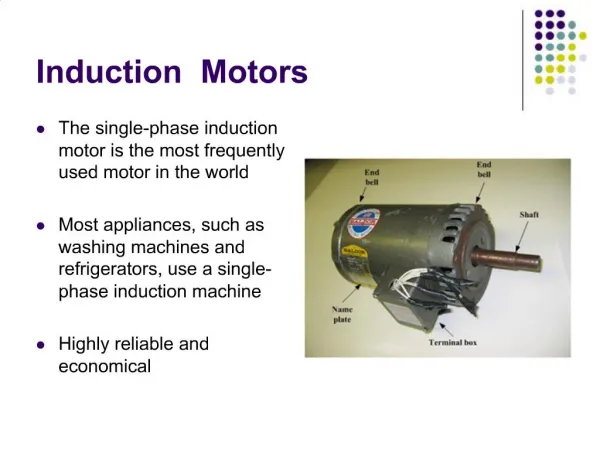
INDUCTION MOTORS 2. … INDUCTION MOTOR INDUCED-TORQUE EQUATION. Z TH =R TH +jX TH = jX M (R 1 +jX 1 )/[R 1 +j(X 1 +X M )] Since X M >>X 1 and X M +X 1 >>R 1 , Thevenin resistance & reactance can be approximated as: R TH ≈ R 1 ( X M / [X 1 +X M ] ) ^2 X TH ≈ X 1

E N D
…INDUCTION MOTOR INDUCED-TORQUE EQUATION ZTH=RTH+jXTH = jXM(R1+jX1)/[R1+j(X1+XM)] • Since XM>>X1 and XM+X1>>R1 , Thevenin resistance & reactance can be approximated as: RTH ≈ R1 ( XM/ [X1+XM] ) ^2 XTH ≈ X1 • resulting equivalent circuit:
…INDUCTION MOTOR INDUCED-TORQUE EQUATION • The current I2 obtained as follows: I2= VTH / (ZTH + Z2)=VTH/[RTH +R2/s + j XTH +j X2] • Magnitude of current: I2= VTH /√(RTH+R2/s)^2+(XTH+X2)^2 • Air gap power PAG = 3 I2^2 R2/s= 3 VTH^2 R2/s / [(RTH+R2/s)^2+(XTH+X2)^2] and rotor induced torque is: Tind=PAG/ ωsync Tind=3VTH^2 R2/s / {ωsync [(RTH+R2/s)^2+(XTH+X2)^2]} a plot of torque as function of speed (& slip) shown in next figure:
…INDUCTION MOTOR INDUCED-TORQUE EQUATION • A typical induction motor torque-speed characteristic curve
…INDUCTION MOTOR INDUCED-TORQUE EQUATION • A plot of speed above & below normal range shown below:
INDUCTION MOTORTORQUE-SPEED CURVE • Torque-speed characteristics curve provides several important information 1- induced torque of motor is zero at syn. Speed 2- torque-speed curve is nearly linear between no load and full load.In this range rotor resistance is much larger than its reactance so rotor current, rotor magnetic field & induced torque increase linearly with increasing slip 3- there is a maximum possible torque that cannot be exceeded (pullout torque) is 2 to 3 times rated full-load torque of motor (calculated in next section) 4-starting torque on motor is slightly larger than its full-load torque, so this motor will start carrying any load that it can supply at full power 5- Note: that torque on motor for a given slip varies as square of applied voltage. This is useful in one form of induction motor speed control that will be described
INDUCTION MOTORTORQUE-SPEED CURVE 6- if rotor of induction motor driven faster than sync. Speed, direction of Tind reverses & machine become Gen. converting Pmech to Pelec (discussed later) 7- if motor turning backward relative to direction of magnetic fields,induced torque will stop machine very rapidly & will try to rotate it in other direction since reversing direction of magnetic field rotation is simply a matter of switching any two stator phases, this fact can be used as a way to very rapidly stop an induction motor act of switching two phases in order to stop motor very rapidly is calledplugging
INDUCTION MOTORTORQUE-SPEED CURVE • Power converted to mechanical in an induction motor: Pconv=Tindωm • Note:peak power supplied by induction motor occurs at a different speed than maximum torque; and of course no power is converted to mechanical form when rotor is at zero speed
INDUCTION MOTORTORQUE-SPEED CURVE • Induced Torque & Power Converted versus motor Speed in r/min (4 pole induction motor)
INDUCTION MOTORTORQUE-SPEED CURVE • Maximum (Pullout) Torque in induction motor • Tind=PAG/ωsync maximum possible torque occurs when air gap power is maximum • Since air-gap power = power consumed in R2/smaximum induced torque will occur when power consumed by this resistor is maximum • If angle of load impedance is fixed, maximum power transfer theorem states : maximum power transfer occur when magnitude of that impedance = source impedance magnitude • Equivalent source impedance: Zsource=RTH+jXTH+jX2 • So maximum power transfer occurs when: R2/s=√RTH^2 + (XTH+X2)^2