Download

1 / 40
400 likes | 435 Views
This design review outlines the mission goals, sizing methods, design trade-offs, and performance analysis of an advanced ESTOL aircraft aimed at relieving congestion and utilizing secondary airports. The aircraft features a composite fuselage, forward swept wing, advanced integrated flight deck, upper surface blowing, and geared turbofan engine.

E N D
Team 3 Marques Fulford Mike Bociaga Jamie Rosin Brandon Washington Jon Olsten Tom Zettel Hayne Kim
Outline • Review of Mission • Walk-Around Diagrams • Design Goals Compliance • Sizing Methods and Results • Design Trade-offs and Visualization • Analysis • Aerodynamics • Propulsion • Performance • Structures • Weights & Balance • Stability & Control • Aircraft Servicing • Environmental Impact
Mission ReviewMission Goal • Relieve continuously growing congestion of large hubs • Utilizing secondary airports with ESTOL • Performing half-runway takeoffs • Non-interfering spiral decent landings • Short – Medium range • 2000 nmi
Mission ReviewUse-case Scenarios • Gary Chicago to Dallas Love Field • 693 nmi • New York LaGuardia to Miami International • 935 nmi • Charlotte International to Essex County, NJ • 460 nmi • Round trip without refueling
Composite Fuselage Forward Swept Wing Advanced Integrated Flight Deck Upper Surface Blowing Geared Turbofan Engine Walk-AroundExterior Extra Large Cabin Windows
Walk-AroundConcealed Components Hydrogen Fuel Cell APU Jet Fuel Wing Tank 50gal Potable Water Tank Hydrogen Fuel Tank Baggage Compartment Nose Gear Main Gear 6
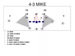
Ground Roll <= 1500ft W/S = 84 lb/ft2 T/W=0.310 SizingCarpet Plot
SizingMethods and Flowchart Input: Fixed Design Parameters Yes • Approach validated with 737 data • Produced sizing results for three mission cases and target and threshold range cases • Aircraft sized to worst-case result • 2000 nmi Target Range Empty Weight Fraction Estimation1 Size Aircraft Weight, Surfaces, Fuel No Empty Weight based on Component Weight2 Final Sizing Results Empty Weights Agree? 1,2 Empty Weight Fraction, Component Weights estimated from methods in “Aircraft Design: A Conceptual Approach” by Daniel P. Raymer
SizingVertical, Horizontal Tails • Horizontal Tail • Sized to provide moment to meet take-off rotation • Vertical Tail • Sized provide one-engine out performance requirement with 20 degrees of rudder deflection
DesignTrade-Offs • Wing moved slightly forward to reduce vertical tail size • Loss of 4 degrees of rotation on takeoff • Tail-strike at 14 deg rotation • Canard replaced by Conventional Tail • Avoid “ramp rash” • Stability – simplicity
18.5 ft 32 ft 102 ft DesignFront View
V. Tail Area: 350 sq ft 35ft 63 ft 10 ft 123 ft DesignSide View
Wing Area: 1032 sq ft 16ft 40ft Fuselage Width: 12ft 4in H. Tail Area: 450 sq ft DesignTop View
DesignTwo-Class Interior – 163 Total Passengers Emergency Exit Rows 36” Seat Pitch First Class Galley First Class Lavatory First Class Galley Economy Lavatories Economy Class: 32” Seat Pitch 147 Passengers First Class: 35” Seat Pitch 16 Passengers 18
DesignSingle-class Interior – 177 Total Passengers Emergency Exit Rows 36” Seat Pitch Forward Lavatory Rear Galley Rear Lavatories All Economy 32” Seat Pitch 177 Passengers Forward Galley 19
AerodynamicsAirfoil Selection • Supercritical airfoils from a Gulfstream GIII selected as representative of a future airfoil selection Potential Flow GIII Mid-Span 2D Airfoil Cl vs. AOA GIII Root Airfoil
AerodynamicsAirfoil Selection • Airfoil section for Vertical and Horizontal tails based off of operational needs of tail components • Symmetric airfoil sections used
AerodynamicsHigh Lift Devices • Continuous flap section where USB has significant impact (inboard) • Double-slotted Fowler Flaps where USB effect is negligible (outboard)
AerodynamicsParasite Drag Buildup Major Aerodynamic Features: • Fuselage • Wing • Vertical Tail • Horizontal Tail • Engine Nacelle Smoothness of Composites reduces Skin Friction, helps maintain laminar flow over a larger section of fuselage, wings CD0 ≈ 0.012
AerodynamicsAircraft Drag Polar • Parasite, Induced, and Wave Drag
To take off with one engine out: Max Thrust (ea.): 26900 lbs Weight (ea.): ~ 4300 lbs SFC (cruise): 0.36 hr-1 Mounted above the wing Upper surface blowing to increase CL,max Turbo-Fan analysis in Hill & Peterson1 used to evaluate engine performance PropulsionGeared Turbo-Fan Bypass Ratio: 12 Fan Pressure Ratio: 1.5 Compressor PR: 20 1 “Mechanics and Thermodynamics of Propulsion” by Hill & Peterson
Altitude: 30,000 ft Vstall 129 kts Vmax 493 kts Vbest range 408 kts Vbest range M = 0.78 PropulsionThrust, Drag vs. Velocity Cruise Altitude: 36,000 ft Vstall 144 kts Vmax 488 kts Vbest range 482 kts
PerformanceFlight Envelope Absolute Ceiling: 51,000 Feet Service Ceiling: 46,000 Feet Cruise Altitude: 36,000 Feet Stall Limit
Corner Speed = 147 knots • Cruise Speed = 447 knots • Dive Speed = 559 knots • Stall Speed = 85 knots PerformanceV-n Diagram
PerformanceCharacteristics • Best Range Velocity: 482 knots • Best Endurance Velocity: 375 knots • Maximum Speed: 488 knots (36,000ft) • Stall Speed: 85 knots • Takeoff Speed: 94 knots • Approach Speed: 128 knots • Total Takeoff Distance: 2600 ft • Total Landing Distance: 2400 ft (5,000ft)
StructuresMaterial Selection • Carbon Fiber Reinforced Plastic • High Strength • Low Weight • 25%+ weight savings over current material • For aircraft 80% composites by weight • Cost will decrease as use becomes commonplace • Fiber Optic Cable (Fly-by-light) • Faster & lighter than copper • Cheaper to maintain
StructuresWing Structure Configuration Landing Gear Kick Spar Engine Mount Wingbox Carrythrough Main Wing Spars Wing Ribs 31
Weight and BalanceStability and Static Margin • Aircraft Length: 123 ft • Forward C.G: 65.4 ft • C.G @ Takeoff: 69.9 ft • Aft C.G: 70.5 ft • Neutral Point: 70.5 ft (MTOW) Center of Gravity Neutral Point
Weight and BalanceControl Surface Sizing • Rotation Angle = 10 deg • Horizontal Tail Area = 450 ft2 • One engine out condition • Vertical Tail Area = 350 ft2
Aircraft ServicingConventional Terminal Servicing • Terminal Servicing without use of APU • Compatible with airports that are using current equipment 36
Aircraft ServicingHydrogen Fuel Cell Terminal Servicing • Servicing Using Hydrogen Fuel Cell APU • Hydrogen Fuel Truck hookup • No Environmental impact • No Waste • Less Equipment • Could potentially eliminate potable water truck
Aircraft ServicingEngine Maintenance Advantages of Design • Easy access to engine core • Easy removal of engine core • Overwing access to engine Disadvantage • Higher off ground than underwing engine 38
Reduced SFC Less fuel burn, emissions Composite Construction Less material use, waste Hydrogen Fuel Cell APU No toxic emissions Quieter Engines Reduced noise pollution Environmental ImpactEmissions and Waste