Download
1 / 19
190 likes | 208 Views
Standardní o ptick á vlákna. Standardní o ptick á vlákna. Standardní o ptick á vlákna. Standardní o ptick á vlákna. Standardní o ptick á vlákna. Standardní o ptick á vlákna. Standardní o ptick á vlákna.

E N D
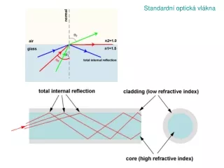
Standardní optická vlákna A gradient-index (GRIN) lens with a parabolic variation of refractive index n with radial distance x. The lens focusses light in the same way as a conventional lens. Využití: rovná plocha, např. konektory pro optická vlákna
Fiber Bragg Gratings Schematic structure of a fiber Bragg grating(FBG). Thefiber corehas a periodically varyingrefractive index over some length. The drawing is notto scale. Typical dimensions: 125 μm claddingdiameter and8 μm corediameter; periods Λof therefractive indexgratings vary in the range of hundredsof nanometers or (for long-period gratings) hundredsof micrometers. Air Encyclopedia of Laser Physics and Technologyhttp://www.rp-photonics.com/encyclopedia.html
Reflectivity spectra of a 5.4 mm long FBG withdifferent refractive index contrast, corresponding todifferent times of exposure to UV light. The side lobesof the reflectivity curve, as observed for a high indexcontrast, could be removed by apodization, i.e., byreducing the index contrast towards the ends of thegrating. Encyclopedia of Laser Physics and Technologyhttp://www.rp-photonics.com/encyclopedia.html
Photonic crystal fibers (PCF) Highindexguiding fibersare analogous to total internal reflection known from standard optical fibers. It relies on a high index core region, typically pure silica, surrounded by a lower effective index provided by the microstructured region. The effective index of such a fiber can, in the simple case, be approximated by a standard step index fiber, with a high index core and a low index cladding
Photonic crystal fibers (PCF) A special class of PBG guiding fibers is the air-guiding fibers, where the field is confined to an air-filled core. Like other PBG fibers, air-core fibers only guide light in a limited spectral region. For fibers guiding around 1550nm, a typical bandwidth is ~200nm. Outside this region, the fiber core is anti-guiding.
Photonic crystal fibers (PCF) A stack of glass tubes and rods is constructed as a macroscopic "preform" with the required photonic crystal structure. It is then fused together and drawn down to fiber in two stages using a standard fiber drawing tower. To soften the silica glass, the furnace runs at 1800° to 2000°C.
Photonic crystal fibers (PCF) (A) Propagation diagram for a conventional single-mode fiber (see schematic in the top left-hand corner) with a Ge-doped silica core and a pure silica cladding. Guided modes form at points like R, where light is free to travel in the core but unable to penetrate the cladding (because total internal reflection operates there). The narrow red strip is where the whole of optical telecommunications operates. (B) Propagation diagram for a triangular lattice of air channels in silica glass with 45% air-filling fraction. In region (1), light is free to propagate in every region of the fiber [air, photonic crystal (PC), and silica]. In region (2), propagation is turned off in the air, and, in (3), it is turned off in the air and the PC. In (4), light is evanescent in every region. The black fingers represent the regions where full two-dimensional photonic band gaps exist. Guided modes of a solid-core PCF (see schematic in the top left-hand corner) form at points such as Q, where light is free to travel in the core but unable to penetrate the PC. At point P, light is free to propagate in air but blocked from penetrating the cladding by the PBG; these are the conditions required for a hollow-core mode. Philip Russell : Photonic Crystal Fibers Science 299, 358-362 (2003)
Photonic crystal fibers (PCF) An assortment of optical (OM) and scanning electron (SEM) micrographs of PCF structures. (A) SEM of an endlessly single-mode solid core PCF. (B) Far-field optical pattern produced by (A) when excited by red and green laser light. (C) SEM of a recent birefringent PCF. (D) SEM of a small (800 nm) core PCF with ultrahigh nonlinearity and a zero chromatic dispersion at 560-nm wavelength. (E) SEM of the first photonic band gap PCF, its core formed by an additional air hole in a graphite lattice of air holes. (F) Near-field OM of the six-leaved blue mode that appears when (E) is excited by white light. (G) SEM of a hollow-core photonic band gap fiber. (H) Near-field OM of a red mode in hollow-core PCF (white light is launched into the core). (I) OM of a hollow-core PCF with a Kagomé cladding lattice, guiding white light. Philip Russell : Photonic Crystal Fibers Science 299, 358-362 (2003)
Photonic crystal fibers (PCF) In a solid-core PCF, the pattern of air holes acts like a modal sieve. In (a), the fundamental mode is unable to escape because it cannot fit in the gaps between the air holes--its effective wavelength in the transverse plane is too large. In (b) and (c), the higher order modes are able to leak away because their transverse effective wavelength is smaller. If the diameter of the air holes is increased, the gaps between them shrink and more and more higher order modes become trapped in the "sieve." Philip Russell : Photonic Crystal Fibers Science 299, 358-362 (2003)
Fig. 5. Particle trapping and guidance in a hollow-core PCF. The van der Waals forces between the µm-sized polystyrene particles (c) are broken by making them dance on a vibrating plate (a). The laser beam (b) captures them and entrains them into the hollow-core PCF (d). Philip Russell : Photonic Crystal Fibers Science 299, 358-362 (2003)
Photonic crystal fibers (PCF) (A) The supercontinuum spectrum produced from an infrared laser operating at 800 nm and producing 200-fs pulses. The infrared light is launched (a) into highly nonlinear PCF (b) and the supercontinuum is dispersed into its constituent colors at a diffraction grating (d). The resulting spectrum is cast on a screen (c). (B) The supercontinuum spectrum consists of millions of individual frequencies, spaced by the ~100-MHz repetition rate of the infrared laser. The resulting ladder can be used as a highly accurate "ruler" for measuring frequency. Philip Russell : Photonic Crystal Fibers Science 299, 358-362 (2003)