Download
1 / 12
130 likes | 490 Views
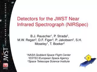
Detectors for the JWST Near Infrared Spectrograph (NIRSpec). B.J. Rauscher 1 , P. Strada 2 , M.W. Regan 3 , D.F. Figer 3 , P. Jakobsen 2 , S.H. Moseley 1 , T. Boeker 2. 1 NASA Goddard Space Flight Center 2 ESTEC/European Space Agency 3 Space Telescope Science Institute. Enter NIRSpec.

E N D
Detectors for the JWST Near Infrared Spectrograph (NIRSpec) B.J. Rauscher1, P. Strada2,M.W. Regan3, D.F. Figer3, P. Jakobsen2, S.H. Moseley1, T. Boeker2 1NASA Goddard Space Flight Center2ESTEC/European Space Agency3Space Telescope Science Institute
Enter NIRSpec A pretty picture is not enough .. Most observations probably detector noise limited! AAS, Atlanta, GA
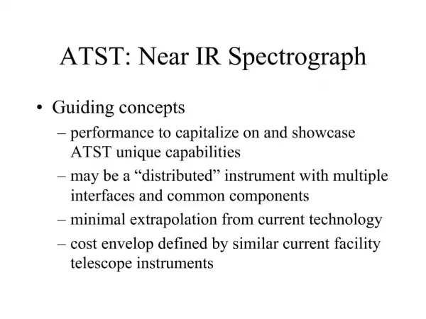
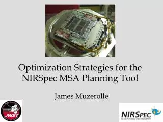
NIRSpec Modes • R=100 (Exploratory spectroscopy, Verify photometric redshifts) • Single Prism 0.6 - 5.0 µm • Micro-Shutter Array or Fixed Slits • R=1000 (Emission line diagnostics) • 3 Gratings 1.0 - 5.0 µm • Micro-Shutter Array or Fixed Slit(s) • R=3000 (Emission line kinematics) • 3 Gratings 1.0 - 5.0 µm • Fixed Slit or Integral Field Unit (TBC) AAS, Atlanta, GA
NASA/GSFC to Contribute • 2K4K HgCdTe FPA • Readout Electronics • Cable Harness NIRSpec • Instrument built by European Industry under ESA Project Leadership • Presently Transitioning from Definition to Implementation Phase • Two NASA-provided components: • 4 x 384 x 175 Micro-Shutter Array • 2 x 2k x 2k HgCdTe Detector Array AAS, Atlanta, GA
Focal Plane Array (FPA) Technology • 2K4K FPA comprised of two 2K2Ksensor chip assemblies (SCAs) • =0.6–5.0 m HgCdTe detectors • FPA passively cooled to T=34–37 K • Very successful Phase-A detectordevelopment! • Raytheon and Rockwell produced outstanding detectors consistent with requirements • =0.6–5.0 m detectors meet challenging requirements (e.g. total noise =6 electrons rms per t=1000 seconds exposure). AAS, Atlanta, GA
Detector Test Results Conversion gain on this andfollowing plots =1.3 e-/ADU Dark current versus temperature
Detector Test Results Dark current histogram
Detector Test Results Sampled-Up-the-Ramp Dark Signal
With reference pixels Without reference pixels Use of Reference Pixels
Detector Test Results Total noise versus number of non-destructive reads
Selected highlightes from prototype testing • Amplifier glow negligible! —Multiple non-destructive reads averaging down noise. • Reference pixels work! —highly effective at removing e.g. Pedestal Drifts. • Dark current very low and independent of temperature at T < 40 K AAS, Atlanta, GA
To learn more about JWSTdetector prototype test results, see Figer, D.F., Rauscher, B.J., Regan, M.W. et al. 2003, “Independent detector testing laboratory and NGST detector characterization project”, Proceedings Of SPIE Vol. 4850, 981 AAS, Atlanta, GA