Download
1 / 29
290 likes | 312 Views
Collaboration to design intelligent carriers for biosensors, tissue engineering, and cell growth using semiconductor wafers and polymer supports. Features polarizable materials and electrostatic forces for novel lifescience applications.

E N D
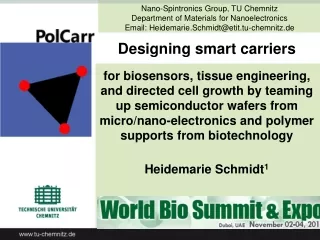
Nano-Spintronics Group, TU Chemnitz Department of Materials for Nanoelectronics Email: Heidemarie.Schmidt@etit.tu-chemnitz.de Designing smart carriersfor biosensors, tissue engineering, and directed cell growth by teaming up semiconductor wafers from micro/nano-electronics and polymer supports from biotechnology Heidemarie Schmidt1
Coauthors • Martin Müller2 • Katarzyna Wiesenhütter3 • Birgit Urban2 • Anne-Dorothea Müller4 • Ilona Skorupa1,3 • Wolfgang Skorupa3 • Michal Rüb5 • Oliver G. Schmidt1,6 1TU Chemnitz, Reichenhainer Straße 39, 09126 Chemnitz, Germany 2Leibniz-Institut für Polymerforschung Dresden e.V., Hohe Str. 6, 01069 Dresden 3 HZDR e.V., Bautzner Landstrasse 400, 01328 Dresden, Germany 4Anfatec Instruments AG, Melanchthonstr. 28, 08606 Oelsnitz (V), Germany 5FH Jena, Fachbereich SciTec, Carl-Zeiss-Promenade 2, 07745 Jena, Germany 6IFW Dresden, Helmholtzstraße 20, 01069 Dresden, Germany
Collaborations & Acknowledgments • K. Wiesenhütter, I. Skorupa, U. Wiesenhütter, A. Kolitsch, W. Skorupa, J. Raff/ Helmholtz-Zentrum Dresden-Rossendorf • O.G. Schmidt/ TU Chemnitz, IFW Dresden • M. Rüb/ EAH Jena • A.-D. Müller/ Anfatec Instruments AG • J. Meyer, D. Teichmann, S. Friedrich-Löbelt, K. Rosenkranz, T. Förster/ Ascenion GmbH • M. Müller, P. Uhlmann/ IPF Dresden • A.-K. Meyer/ Klinik für Neurologie, TU Dresden • J. Pahnke/ SectionofNeuropathology, University of Oslo • O. Deschaumes, C.Bartic/ Soft Matter andBiophysics, KU Leuven • G. Ettenberger/ Pharma, Medizinprodukte und Hygiene, OFI Wien • F.W. Falkenberg / CIRES GmbH
Outlook • Polarizablematerialsandelectrostaticforces • Charge-patternedsiliconwafers • Detectionofsurface-nearelectrostaticforces (SNEF) • Carriers fornonlocalandlocaladsorption ofpolarizablematerials • PolCarrcarriersfornovelapplications in lifesciences • Summary
Polarizablematerialswithelectricdipolep • Molecule where electrons are concentrated in one place has instantaneous dipole p • Molecule with two atoms with different electronegativity has permanent dipole p • Molecule whereelectrons are repelled by permanent dipole • of another molecule has induced dipole p Water molecule in vapour, p=1.85 D Cis isomer, p=1.90 D Trans isomer, p=0 D 6
ElectrostaticforcesF • ChargescreateelectricfieldE. • Long-range (10-100 nm) Coulomb forceF betweencharges • Dipole momentptendstoalign in an electricfieldE + No labeling of polarizable material needed. Many molecules and biomaterials are polarizable. + + - E -- p
Electrostatic forces between molecules Attractive force Repulsive force + + - Anionic polymer Cationic polymer Cationic polymer Advances in Polymer Science 255 & 256 (Ed.: Martin Müller), Springer, 2014
Small charge/area concentration Bottle battery consisting of 25 Leyden jars (inside (+) & outside (-) metal-coated glas) (Deutsches Museum München, Inv. Nr. 3920) Frictional electrostatic generator negative (-) charge on rasps positive (+) charge on glass plate Leyden jar (battery) Charges/area: 1012-1014 e/m2 1 e/(100 nm x100 nm)
Large charge/area concentration F F - - - - - - - - + + + + + + + + 200 kV DANFYSIK 1090, High current ion implanter Implanted silicon wafer Charges/area: 1014-1018 e/m2 1 e/(1 nm x1 nm) 500 kV ion implanter Length scale:1 mm - 1 mm - 1 nm
Detection of surface-near electrostatic forces (SNEF)
Probing SNEF by KPFM Kelvin probe forcemicroscopy (KPFM) • Minimizationofelectrostaticforcesacting on thecantilever (vibrationamplitudefac) byapplyingtheappropriate KPFM bias UKtothe sample backside. • Topography (resonancefrequencyfr, vibrationamplitude ~10 nm) and KPFM bias UK (operationfrequencyfac, vibrationamplitude < 20 pm) probedsimultaneously.
Probing SNEF by KPFM • Minimization of the SNEF • by accumulation of mobile • majority charge carriers in the surface region of the • doped semiconductor • KPFM bias applied to • sample backside is related • with energy difference • between Fermi energy EF • and respective band edge [2] Picture: Sander Münster, Kunstkosmos Doped Si cantilevers (NSC15, k=46 N/m): fac=5 kHz-130 kHz < fr=265 kHz-400 kHz C. Baumgart, M. Helm, H. Schmidt, Phys. Rev. B 80 (2009)
Carriers for nonlocal and local adsorption of polarizable materials:3 Proof-of-Concept (PoC)
Nonlocaladsorptionofpolarizable material Carrier A: Si substrate with polyelectrolyte coating T.J. Günther, M. Suhr, J. Raff, K. Pollmann, Immobilization of microorganisms for AFM studies in liquids, RCS Adv. 4 (2014) 51156
PoCwithmicroorganisms on carrier A A Viridibacillus arvi JG-B58 B Lysinibacillus sphaericus JG-B53, OD600=0.05 C E.coli , OD600=0.10 D E.coli , OD600=0.05 OD600: optical density of cells in a liquid @ 600 nm Successful immobilization for AFM studies in liquids T.J. Günther, M. Suhr, J. Raff, K. Pollmann, RCS Adv. 4 (2014)
Nonlocaladsorptionofpolarizable material Carrier B: Si cantilever with SiO2 coating O. Bäumchen et al., Vom Photolack zum Gecko, Physik Journal 14 (2015) 37-42
PoCwithbacteria on carrier B Hydrophilic surface Hydrophobic surface Frequency in percent Frequency in percent Adhesive power in nN Adhesive power in nN Force F increases with decreasing SiO2 thickness O. Bäumchen et al., Vom Photolack zum Gecko, Physik Journal 14 (2015) 37-42
Localadsorptionofpolarizable material Carrier C: PolCarr carrier Charge-patterned silicon wafer Dipping/spin-coating in/of solution with polarizable material Local attachment of polarizable material on PolCarr carrier H. Schmidt, S. Habicht, S. Feste, A.-D. Müller, O.G. Schmidt, Appl. Surf. Sci. 281 (2013)
Localadsorptionofpolarizable material Diethylaminoethyl-Dextran-FITC (DEAE-FITC) (Ø=10-20 nm (pH=9), l=200 nm (pH=4)) Rinsing (5 min, dest. water) Drying (10 min, 50°C) Dipping at pH=11 (1 mg/ml) Local P-implantation of n+-Si stripes (5 mm width, 15 mm periodicity) into n-Si pH=9 pH=4 Advances in Polymer Science 255 & 256 (Ed.: Martin Müller), Springer, 2014 H. Schmidt, S. Habicht, S. Feste, A.-D. Müller, O.G. Schmidt, Appl. Surf. Sci. 281 (2013)
Positively charged molecule (DEAE-FITC) Cationic polymer diethylaminoethyl-Dextran-FITC (DEAE-FITC) + pH=9 pH=4 + • Monomer molar mass: 231g/mol • Polymer molar mass: 150.000 g/mol • Charges per monomer unit: 0.5 • Branched topology, Labeled with Fluoresceinisothiocyanat/FITC • Coiled chain (pH=9): Ø=10-20 nm • Elongated chain (pH=4): l=200 nm Advances in Polymer Science 255 & 256 (Ed.: Martin Müller), Springer, 2014
10 mm PoCwith DEAE-FITC on carrier C 100% coating of n+-Si-stripes with DEAE-FITC Standard Si wafer: <20% coating
Fabrication of PolCarr carriers Design of photolithography mask Selection of implantation parameters Ionimplantation Dopantactivation Deposition of biocompatible thin film
MicrowellplateswithPolCarrbottomplate Charge-pattern in PolCarr bottom plate (implanted Si wafer) for local attachment of polarizable biomaterials and for adherent cell growth is defined by implantation pattern and by species of implanted ions.
Summary • Charges in implantedsiliconwaferscreate SNEF • SNEF probedby Kelvin probe forcemicroscopy • PolCarrcarrierswith SNEF patternforlocalattachment ofpolarizablematerialsretainingfunctionalityduring: • Autoclavingforsterilization (+121 °C, high pressure steam, 15–20 min) • Incubationforcellgrowth (+37 °C, pH, CO2, O2, N2, hours-days) • Cryogenic applications for shock freezing (-196 °C, days-weeks-months)
Thankyouforyourattention. PD Dr. Heidemarie Schmidt Nano-Spintronics Group Department of Materials for Nanoelectronics Chemnitz University of Technology Email: Heidemarie.Schmidt@etit.tu-chemnitz.de Phone: +49-371 531-32481