Download
1 / 22
220 likes | 331 Views
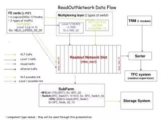
ReadOutNetwork Data Flow. FE cards ( L1FE 1 ) 4 outputs(DAQ)+1(Throttle) 2 types of traffic HLT(1link) Level 1 (up to 3) Ex: VELO_L1FE00_00_00. Multiplexing layer: 2 types of switch. TRM (1 module). HLT (16 I /2 O) ( HLTMS ) Ex:HLTMS_10. Level 1(16I/2O) ( L1MS ) Ex:L1MS_05.

E N D
ReadOutNetwork Data Flow • FE cards (L1FE1) • 4 outputs(DAQ)+1(Throttle) • 2 types of traffic • HLT(1link) • Level 1 (up to 3) • Ex: VELO_L1FE00_00_00 • . • Multiplexing layer:2 types of switch TRM (1 module) HLT (16 I /2 O) (HLTMS) Ex:HLTMS_10 Level 1(16I/2O) (L1MS) Ex:L1MS_05 Readout Network Slot (RNS_Slot1) HLT traffic Level 1 traffic mixed traffic ethernet traffic Sorter RNS_Slot_00 RNS_Slot_15 TFC system (readout supervisor) HLT possible link Level 1 possible link • SubFarm • SFC(94-175)(SFC1), Ex: SFC_02 • Switch(SFC_Switch1): 1I/16 O, Ex: SFC_Switch_02 • CPU (2000 in total)(SFC_Node1) • Ex:SFC_Node_02_13 Storage System 1 component type names : they will be used through this presentation
ReadOutNetwork :6 use cases (1/4) 1. Intrinsic parameters for a switch: A switch has a type (L1MS for example) and a name (L1MS_05) and a hostname. Each switch type is characterized by a number of input and output ports. 2. Intrinsic parameters for a port: A port is identified by a physical address. It is part of a switch. It has a number which can be input or output. It has a status (broken or not). It has a physical implementation link (phy) that is to say it can optical or copper... It has a receiver and a transmitter flow control (respec.RxFC and TxRC) which can be enabled or disabled. It has a set of speed and you can force a specific one. A port can be a port management or not and has a wire sense : it can be switch-switch, switch-computer or autosense.
ReadOutNetwork :6 use cases (2/4) 3. Find the neighboring connections(up or down) of a switch by specifying the direction of the data flow and the type of link Example: I want to know to which port(s) of which switch a L1MS_05are connected, carrying L1 traffic in the down direction. → So it cames out thata link has : - a start identifed by (switch name from, port number from) - an end identified by (switch name to, port number to) - a type (HLT, L1 or mixed) - a status: broken or not which is linked to the status of the involved ports.
ReadOutNetwork :6 use cases (3/4) first link path 1: [(VELO_L1FE00_00_00, 2), (HLTMS_10, 4), HLT] [(HLTMS_10,0),(RNS_Slot_03, 2), HLT]→ Selected path 2 : [(VELO_L1FE00_00_00, 2), (HLTMS_10, 4), HLT] [(HLTMS_10,0),(RNS_Slot_03, 2), HLT]→Selected path 3: [(VELO_L1FE00_00_00, 1), (L1MS_05, 5),L1] [L1MS_05,0),(RNS_Slot_11, 5), L1]→ Not Selected path 4:[(VELO_L1FE00_00_00, 0), (L1MS_05, 1),L1] [L1MS_05,1),(RNS_Slot_11, 5), L1]→Not Selected second link 4. Find all the connection path between 2 components given a switch name,a switch type,the direction of the data flow and a type of thelink. Example: I want to know all the possible connexion paths from VELO_L1FE00_00_00 toRNS_Slot which carrie HLT Traffic. → So it cames out thata path is a sequence of links: Switch to RNS_Slot RNS_Slot_11 HLT traffic Level 1 traffic Switch from VELO_L1FE00_00_00 L1MS_05 0 0 1 0 5 1 5 2 HLTMS_10 4 0 RNS_Slot_03 3 2 8
ReadOutNetwork :6 use cases (4/4) 5. Check that each L1FE can be reached from each SFC_Node that is to say check all the L1FEs and all theSFC Nodes are connected through the RNS_Slot. In other words, a path must exist between each L1FE and aRNS_Slot and a path between each SFC_Node and a RNS_Slot. 6. In the readout network, some of the links are grouped together to form a set of links which is also called a band. A band is found between 2 switches directly connected that is to say there is only one hop. So given a band link number, retrieve all the links belonging to it and vice versa, given a link, find the band link number. Example: I want to know all the links belonging to band link number 5. NB. Not all the links belong to a band link. → it comes out that a band is a collection of links.
Entity relationship model Port + physical address + switch name + nbr + input or output + RxFC (Enable or not) + TxFC (Enable or not) + status (Broken or not) + speed + Port Management(yes/no) + Wire sense (Switch/Switch, Switch/computer, Autosense) + Phy: T, Sx, SL + Forced Speed (Yes/No) Switch Type +Switch type +nbr of input ports +nbr of output ports Switch +Switch Name +Switch type +Host name has 1 n Link +LinkID +Switch Name From +Port Number From +Switch Name To +Port Number To +Type of link Associaton : a link has 2 ports will determine the status of link 1 2 Band link +BandID +LinkID n 1 n 1 Path +PathID +Link
Port + physical @ (pk) + switch name (fk) ref Switch List(Switch_Name) + nbr + in_or_out + RxFC (Enable or not) + TxFC (Enable or not) + status (Broken or not) + speed:(10,100)/(10,100,1000)/ 1000/10.000 Mbit/s + Port Management(yes/no) + Wire sense (Switch/Switch, + Switch/computer, Autosense) + Phy: T, Sx, SL + Forced Speed (Yes/No) Unique(switch name,nbr,in_or_out) Table Design SwitchType +Switch type (pk) +nbr of input port +nbr of output port Switch List +Switch Name (pk) +Switch type (fk) ref SwitchType(Switch_type) +host name 1 n 1 n Switch Connectivity +Switch_LinkID (pk) +Switch_From +Port_nbr_from +Switch_to +Port_nbr_to +link_type (fk) ref Link Type(link nbr) + bidirectional_used + Unique(Switch_From, port_nbr_from) + Unique(Switch_to, port_nbr_to) + Switch_From, Port_nbr_from (fk) ref Port(switch name,nbr,in_or_out=‘out’) + Switch_to, Port_nbr_to (fk) ref Port(switch name,nbr,in_or_out=‘in’) 1 2 Link Type +Link type +Link nbr (pk) 1 n n<11 1 Band Link Link_id (fk) ref SwitchConnectivity(Switch_LinkID) link_band_nbr (pk) Unique(Link_id) bijection READOUTNET_PATH_L1FE +L1FE link_readNet +MS link_readNet +RNS_Slot link_readNet Link_readNet (object) +switch_from (fk) ref Switch List(Switch_Name) +switch_to (fk) ref Switch List(Switch_Name) +port_nbrfrom +port_nbrto +typeOfLink READOUTNET_PATH_SFC +RNS_Slot link_readNet +SFC link_readNet +SFC_Switch link_readNet +SFC_Node link_readNet
TFC SYSTEM X ≤16 used 1 Throttle set of links TFC set of links DAQ set of links TFC set of links sometimes possible ODIN_X Read out s.(?*16) THOR_00 (TFC) 16*16 TTCtx_X transmitter(16*14) X≤16 TTCocX_Y Opt. couplers(1*32) Y≤14 TTCrxX_Y receiver (1*32) TTCrxX_Y_W receiver (1*32) W≤32 Z<16 SubDet_L0FEX_Y_Z (?*1) X≤16 Munin0_X 32*2 SubDet_L1FEX_Y_Z (?*5) DAQ (readout net) MuninL0_00 16*16 MuninL1_00 16*16 SubDet can be (VELO, RICH, L0MUON,...)
TFC_System : use cases (1/3) 1. Intrinsic parameters for a switch: A device has a type (TTCtx for example) and a name (TTCtx_05). Each device type is characterized by a number of input and output ports. 2. Intrinsic parameters for a port: A port is part of a device. It has a number which can be input or output. An output port can be disabled or not. It has a status (broken or not) and a physical location. Each output port has a delay setting which is downloaded once. Each input port of the THOR (switch) is associated with an address. This address consists of the address in hexa of the input port and a output port number. It’s like a routine table. Ex: Input port 1 is associated with (0*1004 , 4) register@ output number NB: Here the device looks like a switch but it is less smart. We use this word to make the distinction between a “true” switch like in the readout network system.
TFC System : use cases (2/3) 3. Find the neighboring connections(up or down) of a switch by specifying the direction of the data flow and the type of link Example: I want to know to which port(s) of which switch a TTCtx_05are connected, carrying TFC traffic in the down direction. → So it cames out thata link has : - a start identifed by (switch name from, port number from) - an end identified by (switch name to, port number to) - a type (TFC, throttle or DAQ) - a status: broken or not which is linked to the status of the involved ports.
TFC System : use cases (3/3) first link second link path 1: [(VELO_L0FE00_00_00, 0), (TTCrx00_00_00, 0), TFC] [(TTCrx00_00_00, 0),(TTCoc00_00, 0), TFC] [(TTCoc00_00,0) , (TTCtx_00,0), TFC]->Selected path 2: [(VELO_L0FE00_00_00, 1), (TTCrx00_00_11, 0), TFC] [(TTCrx00_00_11, 0),(TTCoc00_00, 11), TFC] [(TTCoc00_00,0) , (TTCtx_00,0), TFC]->Selected third link 4. Find all the connection path between 2 components given a switch name,a switch type,the direction of the data flow and a type of thelink. Example: I want to know all the possible connexion paths from TTCtx toVELO_L0FE00_00_00 which carrie TFC Traffic. → So it cames out thata path is a sequence of links: TTCrx00_00_00 0 Switch from VELO_L0FE00_00_00 0 0 0 0 TTCoc00_00 TTCtx_00 0 1 TTCrx00_00_11 0 11 0
Entity relationship model Device Type +Device type +nbr of input ports +nbr of output ports Device +Switch Name +Switch type has Port + physical location + switch name + nbr + input or output + status (Broken or not) + Output_Disabled + Delay_setting 1 n Link +LinkID +Switch Name From +Port Number From +Switch Name To +Port Number To +Type of link Associaton : a link has 2 ports will determine the status of link 2 1 n 1 Path +PathID +Link
Table Design DeviceType +device type (pk) +nbr of input port +nbr of output port Port + physical location (pk) + switch name (fk) ref Switch List(Switch_Name) + nbr + in_or_out + status (Broken or not) + Output_Disabled(on/off) + Delay_setting number. Unique(switch name,nbr,in_or_out) Device +Switch Name (pk) +Switch type (fk) ref SwitchType(Switch_type) 1 n 1 n TFC Connectivity +Switch_LinkID (pk) +Switch_From +Port_nbr_from +Switch_to +Port_nbr_to +link_type (fk) ref Link Type(link nbr) + bidirectional_used + Unique(Switch_From, port_nbr_from) + Unique(Switch_to, port_nbr_to) + Switch_From, Port_nbr_from (fk) ref Port(switch name,nbr,in_or_out=‘out’) + Switch_to, Port_nbr_to (fk) ref Port(switch name,nbr,in_or_out=‘in’) 1 2 Link Type +Link type +Link nbr (pk) 1 n TFC_PATH_ODIN00 +tfc_pathid +THOR +TTCtx +TTCoc +TTCrx +L0FE +L1FE +Munin0 +MuninL READOUTNET_PATH_SFC +tfc_pathid +THOR +TTCtx +TTCoc +TTCrx +L0FE +L1FE +Munin0 +MuninL +ODIN bijection Link_readNet (object) +switch_from (fk) ref Switch List(Switch_Name) +switch_to (fk) ref Switch List(Switch_Name) +port_nbrfrom +port_nbrto +typeOfLink view
Use Case triggers • From the CfDB to PVSSDB • insert and update values • makes translation between values • From the PVSSDB to CfDB • if a device is required by an user, download the parameters such nb of input, output into the different tables • if a user makes new changes, make the updates or insert in the cfDB
Use Case for partioning • Characteristics of a partition • A partition is a set of devices which can be run independtly. • A device belongs to one active partition. • A partition in the TFC system will be characterized by an ODIN number and (one or several subdetector(s) OR one or several TTCtx(s)): thus there is a starting and a final point. • In the DAQ system, a partition will stop at the level of SFC: SFC_Switch and SFC_Node are not included. • A partition is associated with a running mode, a version number and an owner. It will be active or not. • A partition is either predefined(linked to one subdetector) or customized. • A customized partition will be created from predefined one(s). Hence the need to write scripts to download them. • Check the compatibility between the different running partitions, and between different created partition -> In fact a partition is a projection (a view) of the TFC_Path:
Use Case for partioning 2)Characteristics of a running mode (or “ activity”) • A running mode is defined by the user: some are already predefined(test, debugging,physic running mode). It has a priority. • Ex of running mode: • calibration & alignment • cosmics • physics (the highest priority) 3) The identity card of a device. • A device is fully identified by a word of 128 bits which consists of: • a system ID • a board type • a revision number • a serial number
Implementation requirements for the user interface • From a user interface (for ex. within PVSS), the user should: • load a selected predefined partition from the Conf.DB • load a previous created customized partition from the Conf.DB • create a customized partition and store it in the Conf.DB • run any partition (from PVSS) provided that it satisfies all requirements. • configure the THOR routine table and store it in the Conf.DB
THOR routine table • Associated with a Partition number • Identified by a number • The way it is stored in the database (cf schema below): • input : 0 0 0 0 0 1 0 0 0 0 0 0 0 0 0 0 • output : 0 0 0 1 0 0 0 1 0 0 0 0 0 0 1 0 • like words of 16 bits: 1 indicates the port is busy. • possible because output ports are driven only by one input port. THOR switch 0 1 2 3 4 5 6 7 8 9 10 11 12 13 14 15 connection busy 0 1 2 3 4 5 6 7 8 9 10 11 12 13 14 15
Implementation requirements for the user interface • Implement scripts to check that : • the user has the rights to create and/or run partitions: (for ex. a guy from the VELO can create only partitions relating to VELO FE cards). • the selected ODIN for a running a partition is still free. • the routine THOR table is coherent with the partition(same ODIN and TTCtx names used in both cases for ex.) • this partition can be performed along with the running ones. • if it is a physic running mode(and the first one), an alert should be sent to other running partitions to warn them and also to stop all the running partitions. • the ended and started time are empty when the partition stops running, in the Conf.DB. • Create datapoint type and datapoints (up to 12 : maximum nb of independent partition, for ex.)which can be to fit partitions structure (for PVSS)
Entity relationship model Thor Routine RoutineId PartitionId Device name Output status Input status Predefined_Partition PartitionId_Version Number Owner ODIN_name Started point Final point Running Mode Active Customized_Partition PartitionId Version Number Owner ODIN_name Started point Final point Running Mode Active HAS HAS 1 1 1 1 Running Mode Mode_name Author Date of creation Priority HAS HAS 1 1 1 1
Thor Routine RoutineIdnumber(pk) THOR_name(fk) references device_list(devname) Output _port _nbnumber Output _port _@ varchar Input _port_nbnumber unique(THOR_name,output_port_nb) Running Mode RunMode_namevarchar (pk) Author varchar Date of creation date Priority number TFC_Partition PartitionId_VersionNb varchar Owner varchar ODIN_name(fk) references device_list(devname) Start_End link_readnet Active number PartitionId_VersionNb, Start_End (pk) Partit_Act PartitionId_ VersionNb varchar (fk) references TFC_Partition (PartitionId_ VersionNb) RunMode_name varchar (fk) references Running Mode(RunMode_name) unique(partitionid_VersionNb, RunMode_name) Partit_Thor_routine PartitionId_ VersionNb varchar (fk) references TFC_Partition (PartitionId_ VersionNb) RoutineId varchar (fk) references Thor Routine(RoutineId) unique(partitionid_VersionNb, RoutineId) Link_readnet switch_from:starting point switch_to: final point port_nbrfrom:port nbr starting point port_nbrto:port nbr final point link_type:0 for predefined part., 1 for cust. exclusion, 2 for cust. inclusion LinkId:tfc_path_id
SFC_Node SFC_Node name: varchar 2 IP @: control /data varchar 2 Ethernet @ : varchar Physical @ : varchar Type :varchar Kernel Image(location) : varchar Initrd image(location): varchar Control PC name: varchar IP @: varchar 1 Ethernet @ : varchar Physical @ : varchar Type :varchar Kernel Image(location) : varchar Initrd image(location): varchar SFC 1 supervised SFC 2 supervised