Download
1 / 28
300 likes | 490 Views
Data Communications to Train From High-Altitude Platforms. Andy Wang. Paper. George P. White, Yuriy V. Zakharov, “ Data Communications to Trains From High-Altitude Platforms ”, IEEE TRANSACTIONS ON VEHICULAR TECHNOLOGY, VOL. 56, NO 4, pp2253-2266, July 2007. Other reference:

E N D
Data Communications to TrainFrom High-Altitude Platforms Andy Wang
Paper • George P. White, Yuriy V. Zakharov, “Data Communications to Trains From High-Altitude Platforms”, IEEE TRANSACTIONS ON VEHICULAR TECHNOLOGY, VOL. 56, NO 4, pp2253-2266, July 2007 • Other reference: • Lecture note of “Signal Detection and Estimation” from website • Lecture note of “Direction of Arrival Estimation” from website
Summary • Analyze communications to multiple moving trains from High-Altitude Platform (HAP) and proposed array signal processing techniques • Direction-of-Arrival (DOA) estimation • Proposed SIC based Root-MUSIC DOA method • DOA tracking with Extended Kalman Filter (EKF) • Multiple train scenarios (crossing/passing/shadowing) • Compare Conventional BF and Null-steering BF
Outline • Background • DOA • EKF • UL Beamforming • Simulation Results • Conclusions
Background • Existing high data rate service to train combine satellite and terrestrial cellular link • Higher speed Line-of-Sight (LoS) connections through satellite link • Lower speed connection maintenance with multiple terrestrial cellular links • In stations or tunnels
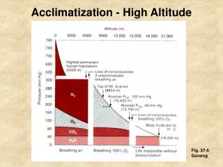
High-Altitude Platform (HAP) • Airplanes or airships positioned at stratospheric altitudes (17-22km) providing wide area wireless coverage • 31/28 GHz band • Elevation angle 0 ≦ θ ≦ π/3 • Azimuth angle 0 ≦ Φ ≦ 2π
To discuss • DOA estimation required to create LoS link • Nondata-aid method preferred • Consider multiple train scenario • Tracking using Kalman Filtering • To reduce DOA estimation variance • Uplink beamforming technique • To reduce interference while train-crossing/passing
DOA Estimation N signals θm Delay=(m-1)dsinθm 1 2 M d sensor array • Correlation-based Method • Multiple Signal Classification (MUSIC) • Root-MUSIC • Source (train) number estimation • Proposed SIC-based Root-MUSIC approach Output of the sensor array r(k)=As(k)+n(k), k=1…K (snapshot) A=[a1,…..,aN]: direction matrix an=[1,e-j(2π/λ)dsinθn,…, e-j(2π/λ)(M-1)dsinθn]T: Direction vector for the nth source
Correlation-based Method N signals θm Delay=(m-1)dsinθm 1 2 M d sensor array • Define received signal r(k), k: snapshot (or sample) • Steering vectors • Correlation-based method (Bartlett’s method)
MUSIC: Principle N signals θm Delay=(m-1)dsinθm 1 2 M d sensor array • Correlation matrix of array data • R=ARsAH+σ2I • Eigen-decomposition on R R s: signal correlation matrix σ2: noise variance Output of the sensor array r(k)=As(k)+n(k), k=1…K (snapshot) A=[a1,…..,aN]: direction matrix an=[1,e-j(2π/λ)dsinθn,…, e-j(2π/λ)(M-1)dsinθn]T: Direction vector for the nth source signal subspace noise subspace • Since signal subspace⊥noise subspace, • DOAs are the peak locations of • MUSIC spectrum
MUSIC: Steps M-N M-N N N v vH • Form the correlation matrix of array output K: snapshot (or samples) • Perform eigen-decomposition to yield noise eigenvectors vN+1,….,vM • Find the peak locations of the MUISC spectrum through • exhausted search (by changing a(θ) ) * note: number of source N is unknown (to be discussed later)
RM-MUSIC concept N signals θm Delay=(m-1)dsinθm 1 2 M d sensor array • Polynomial-based method • Let z=ej(2π/λ)dsinθ peak in correspond to roots of C(z) • There are (M-1) pairs zeros. Choose the N closest to the unit circle
RM-MUSIC Steps • Form the correlation matrix R of array output and find its eigen-decomposition R=QΛQH • Partition Q to yield the noise subspace Qn. Find C=Qn(Qn)H • Obtain Cl by summing the l–th diagonal of C • Find the (M-1) pairs zeros. Choose the N closest to the unit circle (zn, n=1,…N) • Θn=sin-1[angle(zn)] * note: both these two method need to figure out signal/noise subspace
Source (train) number estimation • Use minimum Description Length (MDL) criteria • Number of array element N = (number of signal d) + (number of noise eigen-values) • Estimate the closeness of the eigen-values to figure out the number of signal MDL penalty function * Reference
Proposed SIC-RM approach Estimate number of signal first Extend RM approach to X- and Y-axis Substrate noise of estimated signal
DOA tracking with EKF • Kalman Filter (KF) • Extend KF (EKF) to non-linear model
Kalman Filter • Estimate the state at each time in the sense of minimum mean square error • Linear, IIR filter. Optimum if noises and initial state are all Gaussian. Kalman State Vector Motion update matrix Position in X- & Y-axis Velocity in X- & Y-axis T= measurement period = 5 seconds in this paper * Please refer to course “Adaptive Signal Processing” CH9 for more detail
Measurement Model Cost function
Extended to non-linear model • Since measurement model (DOA) is non-linear, we need to extend kalman filter through determining the Jacobian transformation
Kalman Prediction • Kalman prediction is defined as • And Kalman gain is derived by Assume constant velocity Assume constant velocity Innovation sequence Kalman gain Kalman state error covariance matrix process noise measurement error covariance matrix Innovation process covariance matrix
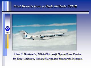
UL Beamforming • Two approaches rely on the estimated steering vectors determined by the DOA estimation method were discussed • Bartlett BF (DOA-steering) • Capon BF (null-steering) *Output of beamformer y(t)=wHx(t) Reference/Figure source: “Convex Optimization-Based Beamforming” Reference
Bartlett BF (Conventional BF) • Bartlett BF (DOA-steering) • The weights were designed to maximum the mean output power Steering vector signal Signal in look direction Signal after beamformer Mean output power P(w)=E [y(t) y*(t)]
Capon BF (null-steering) The true co-variance matrix J: snapshot or samples Recal that output of beamformer y(t)=wHx(t) solution is • Cancelling the wave from known direction • Minimize the co-variance matrix
Performance evaluation Beam-pattern gain Rx noise figure Noise power Boltzman constant Antenna noise Received signal power Bandwidth • The author derive the SINR equation for trains base on the link-budget parameters of HAP. And simulation shows that the Capon BF (null-steering) acquire better performance in train crossing/passing scenarios.
Simulation scenarios • Position estimation • Single train DOA • Multiple train DOA+EFK with • Train crossing/passing • Train in/pass tunnel and station • Prediction and Convergence situation • UL SINR with 2 BF scheme and 2 position estimation scheme (DOA only v.s. DOA+EKF) • Influence of BS motion in HAP • Today we will not show these simulation results
DOA estimation simulation One train with v=300km/h RM-DOA estimation interval: 5 s
Conclusions • Analysis of DOA estimation, tracking and UL beamforming scheme in HAP • Proposed SIC based RM-DOA estimation • Simulate with DOA-EKF tracking • Simulation shows that null-steering technique result better performance in UL multiple train scenario • Simulate various kind of scenario • Based on HAP UL link budget