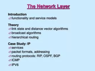
The Network Layer
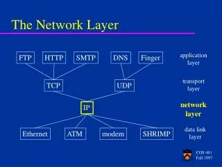
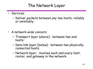
The Network Layer. Services: Deliver packets between any two hosts, reliably or unreliably. A network-wide concern: Transport layer (above): between two end hosts. Data link layer (below): between two physically connected hosts.

The Network Layer
E N D
Presentation Transcript
The Network Layer • Services: • Deliver packets between any two hosts, reliably or unreliably. • A network-wide concern: • Transport layer (above): between two end hosts. • Data link layer (below): between two physically connected hosts. • Network layer: involves each and every host, router, and gateway in the network.
Architectural Approaches • Connectionless - similar to postal system; endpoint puts data to send into a packet and hands to network for delivery • Connection-oriented - similar to telephone system; endpoints establish and maintain a connection as long as they have data to exchange
Connectionless (Datagram) Service • No connection established • Source of data adds destination information to data and delivers to network • Network delivers each data item individually • No routes set up at connection establishment time - each packet may follow different route to destination (but typically won’t). • No guarantee of reliable, or in-order delivery (although data link layer may still do link-by-link error control). • Advantages: • Robust with respect to node / link failures. • Recovery at end to end (transport) level. • Examples: IP
Connection-oriented Service • One endpoint requests connection from network • Other endpoint agrees to connection • Computers exchange data through connection • Typically uses a “stream” interface • Source delivers stream of data to network • Network breaks into packets for delivery • Data transmission not necessarily continuous; like telephone, connection remains in place while no data transmitted • One endpoint requests network to break connection when transmission is complete • Examples: Asynchronous Transfer Mode (ATM), X.25
Connection duration and persistence • Connections can be made on-demand or set up permanently • Switched connection or switched virtual circuit • Permanent connection or provisioned virtual circuit • Permanent connections • Originally hard-wired • Now configured at system initialization • Switched connections • Computer maintains permanent connection to network • Network makes connection on demand
Virtual circuits • Virtual: acts like a circuit, but isn’t really one. • “Reliable” delivery of packets between end hosts. • All packets within connection follow the same route. A D two VCs share link B-C B C E F
Virtual circuits (2) • At connection establishment time: • Connection setup packet flows from sender to receiver. • Routing tables updated at intermediate nodes to reflect new virtual circuit (VC). • Fits well with quality of service (QoS) guarantees: reject call on path if QoS can’t be guaranteed. • Potential difficulty: recovery from link or router failure.
Asynchronous Transfer Mode (ATM) - 160-bit address, 28-bit connection identifier Connection identifier includes: 12-bit virtual path identifier(VPI) 16-bit virtual circuit identifier (VCI) Connection identifier local to each computer May be different in different parts of the ATM switch Address is a complete, unique identifier Connectionless delivery requires address on each packet Connection-oriented delivery can use a shorthand that identifies the connection rather than the destination Address and Connection Identifiers
Internetworking • In the real world, computers are connected by many different technologies • Internetworking is a scheme for interconnecting multiple networks of dissimilar technologies • Uses both hardware and software • Extra hardware positioned between networks • Software on each attached computer • System of interconnected networks is called an “internetwork” or an internet
Routers • A router is a hardware component used to interconnect networks • The router is the main layer 3 building block for large internets. • A router has interfaces on multiple networks • Networks can use different technologies • Router forwards packets between networks • Transforms packets as necessary to meet standards for each network
Internet Architecture • An internetwork is composed of arbitrarily many networks interconnected by routers • Routers can have more than two interfaces
A virtual network • Internetworking software builds a single, seamless virtual network out of multiple physical networks • Universal addressing scheme • Universal service • All details of physical networks hidden from users and application programs Net 2 Net 3 Net 1
A virtual network • Internetworking software builds a single, seamless virtual network out of multiple physical networks • Universal addressing scheme • Universal service • All details of physical networks hidden from users and application programs Net 2 router Net 3 Net 1 Physical network
Internetworking Protocols • TCP/IP is the mostly widely used internetworking protocol suite • First internetworking protocol suite • Initially funded through ARPA • Picked up by NSF • Others include IPX, VINES, AppleTalk • TCP/IP is by far the most widely used • Vendor and platform independent
Internet addresses • One key aspect of virtual network is single, uniform address format • Cannot use hardware addresses because different technologies have different address formats • Address format must be independent of any particular hardware address format • Sending host puts destination internet address in packet • Destination address can be interpreted by any intermediate router • Routers examine address and forward packet on to the destination
IP addresses • Addressing in TCP/IP is specified by the Internet Protocol (IP) • Each host is assigned a 32-bit number • Called the IP address or Internet address • Unique across entire Internet • Each IP address is divided into a prefix and a suffix • Prefix identifies network to which computer is attached • Suffix identifies computer within that network • Address format makes routing efficient
Network and Host Numbers • Every network in a TCP/IP internet is assigned a network number. • Each host on a specific network is assigned a host number or host address that is unique within that network. • Host's IP address is the combination of the network number (prefix) and host address (suffix) • Network numbers must be unique. • Host addresses may be reused on different networks; combination of network number prefix and host address suffix will be unique. • Assignment of network numbers must be coordinated globally; assignment of host addresses can be managed locally.
IP address format • IP designers chose 32-bit addresses (see RFC 790) • Allocate some bits for prefix, some for suffix • Large prefix, small suffix - many networks, few hosts per network • Small prefix, large suffix - few networks, many hosts per network • Because of variety of technologies, need to allow for both large and small networks • Designers chose a compromise - multiple address formats that allow both large and small prefixes • Each format is called an address class • Class of an address is identified by first four bits
Dotted Decimal Notation • 32 bits divided into 4 octets • Each octet is converted to decimal value • Dots used to separate the 4 decimal values • Examples:
IP addresses in C/C++ From /usr/include/netinet/in.h /* Internet address * This definition contains obsolete fields for * compatibility with SunOS 3.x and 4.2bsd. The * presence of subnets renders divisions into fixed * fields misleading at best. New code should use * only the s_addr field. */ struct in_addr { union { struct { u_char s_b1,s_b2,s_b3,s_b4; } S_un_b; struct { u_short s_w1,s_w2; } S_un_w; u_long S_addr; } S_un; #define s_addr S_un.S_addr /* should be used for all code */ };
Useful function calls unsigned long inet_addr( char* cp ) • Converts string with dotted address to 32 bit value • Example: inet_addr(“129.0.0.1”) socketAddress.sin_addr.s_addr = inet_addr( charIPAddress ); char* inet_ntoa(struct in_addr in) • Converts 32 bit value of IP address to a string in dotted decimal format.
IP Addresses in Java • Class java.net.InetAddress static InetAddress getByName(String host) • Creates new instance ofInetAddressbased on a string address • String can either be a dotted decimal IP address (e.g. “129.0.0.1”), or a host name static InetAddress getByAddress(byte[] address) • Creates new instance ofInetAddressbased on bytes containing the 4 values for the IP address String getHostAddress( ) • Returns the IP address as a dotted decimal string byte[] getAddress( ) • Returns the raw IP address as an array of bytes
IP Address Classes Class Octet 1 Octet 2 Octet 3 Octet 4 1.0.0.1 to 126.255.255.254 0 prefix suffix A 128.0.0.1 to 191.255.255.254 10 prefix suffix B 192.0.0.1 to 223.255.255.254 110 prefix suffix C 224.0.0.0 to 239.255.255.255 1110 multicast D 240.0.0.0 to 254.255.255.255 1111 reserved for future use E
CIDR addresses • CIDR = Classless Internet Domain Routing • Created to allow more flexibility in subnet sizes; in particular, different values between 256 and 65536 • Notation: IP address / # bits in prefix • Usage: • Set up 32 bit mask with indicated number of 1 bits followed by 0 bits • Logical AND with mask and IP address to get network prefix
CIDR Example • Example: allocate 2 sub-networks that can hold 14 hosts each • Prefix calculated by logical AND: • Network 1: 128.211.0.16 / 28 ← 28 bits in prefix • Network 2: 128.211.0.32 / 28 • Mask is: 11111111 11111111 11111111 11110000 • Net 1: 10000000 11010011 00000000 0001–––– • Allows IP addresses 128.211.0.17 through 128.211.30, since suffix cannot be all 0s or all 1s. • Net 2: 10000000 11010011 00000000 0010––––
Routers and IP addressing • IP address depends on network address • What about routers - connected to two networks? • IP address specifies an interface, or network attachment point, not a computer • Router has multiple IP addresses - one for each interface Ethernet 131.108.0.0 131.108.99.5 Token Ring223.240.129.0 223.240.129.2 223.240.129.17 76.0.0.17 WAN 76.0.0.0
IP – Internet Protocol Bits 0 4 8 16 19 31 Version IHL Service type Total length Identification Flags Fragment offset Time to live Protocol Header Checksum Source address Destination address Options Data: up to 65,516 octets Maximum packet size: 65,536 octets
IP protocol fields • Definition: RFC 791, plus subsequent additions • Version: version number of protocol (currently 4; version 6 also standardized) • Internet Header Length (IHL): number of 32-bit words in header • Minimum value: 5 (which indicates no options) • Larger values used when options are present.
IP protocol fields • Type of service: • Specifies, precedence (bits 0-2), delay (bit 3), throughput (bit 4), reliability (bit 5) parameters • 0 bit = normal, 1 bit = exceptional • Total length: length of packet in octets • Identification: sequence number • Flags (3): • More: indicates packet is a fragment, with more to come • Don’t fragment: prohibits fragmentation • (Reserved for future use)
IP Protocol Fields • Fragment offset: Indicates where in original datagram, measured in 64-bit units • Note that this requires fragmentation happen at 64-bit boundaries (except for last fragment) • Time to live: specifies, in seconds, time remaining before this packet expires • Every router must decrease this value by at least one. • Protocol: indicates protocol at next higher level • Current list:http://www.iana.org/assignments/protocol-numbers • Examples • 1: ICMP Internet Control Message Protocol • 6: TCP Transmission Control Protocol • 17: UDP User Datagram Protocol
IP Protocol Fields • Header checksum: • 16 bit ones-complement addition of all 16 bit words in the header • Set to zero before computation • Re-computed at each router • Some fields, such as time-to-live will change as message travels through network • Source address: 32 bit IP address • Destination address: 32 bit IP address
IP options • Defined in RFC 791 and others • Examples: • Secure packet • Routing information provided • Record route • Record time stamps • Stream identifier
where: src = source address dst = destination address prot = protocol TOS = type of service TTL = time to live BufPTR = buffer pointer len = length of buffer Id = Identifier DF = Don't Fragment opt = option data IP upper level interface • Two service primitives: send and receive (recv) • Result = SEND(src,dst,prot,TOS,TTL,BufPTR,en,Id,DF,opt) • Result = RECV(BufPTR,prot,&src,&dst,&TOS,&len,&opt)
Internet Control Message Protocol (ICMP) • Defined in RFC 792, plus updates • Required for internet compliance • Carried in IP packets • ICMP messages often sent as a reply to IP packet Bits 0 4 8 16 31 Type Code Checksum Parameters Message content: variable length
ICMP message types 8: Echo 0: Echo reply • Asks for return of this message for testing • Parameters: identifier, sequence number 3: Destination unreachable • Code indicates particular condition: 0: net unreachable 1: host unreachable 2: protocol unreachable 3: port unreachable 4: fragmentation required; don’t fragment flag set 5: source route failure • Data: original IP header, plus first 64 bits of data
ICMP message types 4: Source quench • Request to slow sending rate of IP packets • Data: as in destination unreachable 5: Redirect • Used to indicate a shorter routing path • Parameters: IP address of suggested router 11: Time exceeded • Time to live counter of IP packet reached zero • Data: as in destination unreachable 12: Parameter problem • Indicates problems with an IP message (usually bad option format) • Data: as in destination unreachable
ICMP message types 13: Timestamp • Sends message that records sending time, and asks for reply • Data: sending time, reception time (to be filled in), reply sending time (to be filled in) 14: Timestamp reply • Reply to timestamp request • Data: values filled in from ICMP 13 message 17: Address mask request • Host asks router on LAN for CIDR address mask (usually at reboot) 18: Address mask reply • Reply to address mask request • Data: the address mask
Network administration functionsthat use ICMP • Ping: test if a host will respond • Sends an ICMP echo message to designated host • Host sends ICMP echo reply • Used to test connectivity • Many organizations have disabled ping to prevent denial-of-service attacks • Traceroute: find route from source to destination • Sends IP packet with time-to-live of 1 • First router will discard packet and send ICMP time exceeded message • Next message sent has time-to-live of 2, and so on until destination is reached • Each router en route will have sent an ICMP message
Mapping IP addresses • Problem: How to map IP addresses onto hardware? • Address resolution • Where this takes place: router attached to physical network. • Three methods used to resolve addresses: • Table lookup • “Computation” • Message exchange
Resolution using Table Lookup • Router keeps table. • The following could be a table for network 197.15.3.0 / 24 • To save space and time, only the host value of the IP address would be stored.
Resolution using Computation • If hardware addresses are configurable, they can be assigned to correspond with the host part of their IP address • Example: • host with IP address 229.123.1.1 is assigned hardware address 1; • host with IP address 229.123.1.2 is assigned hardware address 2; • … and so on. • Computation: logical AND with value 000000FF. hardware_address = ip_address & 0xff
Resolution using Message Exchange • Example: Ethernet Address Resolution Protocol (ARP) • See RFC 826 • Router sends broadcast ARP message to LAN to query hosts as to who matches the IP address • Only the host with the matching IP address replies directly to router • Router then has hardware address
ARP message format • There is a generic format in RFC 826 • The following is specific for Ethernet: 32 bit protocol (P) addresses and 48 bit hardware (H) addresses Bits 0 8 16 31 Hardware address type: 0001 Protocol address type: 0800 H. addr. length P. addr. length Operation Sender’s hardware address, part 1 Sender’s H. address pt. 2 Sender’s P. address pt. 1 Sender’s P. address pt. 2 Target H. address pt. 1 Target hardware address, part 2 Target protocol address
Transmission of ARP messages Ethernet frame ARP packet Frame type Preamble SFD Source Addr. Dest. Addr. 0806 data CRC 7 1 6 6 2 46 – 1500 4 octets octets ARP Padding 28 18 octets
IP Fragmentation and Reassembly • Construction of an IP packet requires obeying maximum frame sizes at each data link layer • MTU: maximum transmission unit • Example: IP packet carried inside an Ethernet frame (see next slide) can have, at most, 1478 octets of user data + 20 octets of IP header = 1498 • RFC 791 says any part of the internet must have an MTU 68 octets • Any host must be able to receive 576 octets (possibly in fragments) • If the IP “don’t fragment” flag is set, and there is more data than the MTU allows, a router will trash the IP packet and send an ICMP message (more on this later). • Otherwise, router has to separate user data into fragments of allowable size. • Fragmentation can be done at any router; reassembly is only done at final destination.
Example of MTU: Ethernet frames Ethernet frame IP Packet Frame type Preamble SFD Source Addr. Dest. Addr. 0800 data CRC 7 1 6 6 2 46 – 1500 4 octets 1500 ( = MTU) octets IP Source Addr. Dest. Addr. Layer 4 data 24 – 1480 12 4 4 octets
TL=1500, FO=0, more=1 User data: 1480 octets 20 Example of Fragmented Data User data: 2276 octets With an MTU of 1500, this could be sent as: TL=816, FO=185, more=0 User data: 796 octets 20 TL = total length, FO = frame offset (in 8-octet/64-bit units)
TL=1500, FO=0, more=1 1480 TL=820, FO=0, more=1 800 TL=700, FO=100, more=1 680 TL=816, FO=185, more=0 796 IP Fragmentation • The frame offset is used instead of a “fragment sequence number” because this allows for further fragmentation at a subsequent router TL=816, FO=185, more=0 796 MTU = 820: