Download
1 / 45
470 likes | 861 Views
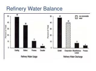
Water Management in a Petroleum Refinery. by: Amy Frink, Timilehin Kehinde, and Brian Sellers. Background. In refineries, water is a crucial part in removal of contaminants from crude oil Desalting Steam cracking Sweetening Hydrotreating Distillation. Crude fractionation unit.

E N D
Water Management in a Petroleum Refinery by: Amy Frink, Timilehin Kehinde, and Brian Sellers
Background • In refineries, water is a crucial part in removal of contaminants from crude oil • Desalting • Steam cracking • Sweetening • Hydrotreating • Distillation Crude fractionation unit
Background • Water re-use as a practical way to reduce freshwater intake • Reduces wastewater treatment costs • Lessens need to comply with government standards for pollution levels • Relieves need to obtain larger amounts of freshwater (costly and limited) • Promotes a greener environment
Goals • Mathematical programming becoming main approach to solving water allocation problem • Optimize stream placement between water-using and wastewater treatment processes by performing mass and contaminant balances • Current methods rely on assumption of fixed outlet concentrations • However, outlet concentration has shown to be a function of pressure, temperature, Cin, etc.
Refinery Schematic • Highlights water-using and regeneration processes Red: Water-using units Green: Conventional water regeneration processes (i.e. end-of-pipe treatment)
Water Treatment Units • Regeneration processes* *Typical refinery standards
API Separator • API separator • Separates suspended solids and oil from wastewater streams based on differences in specific gravities between the oil and the wastewater • Particles settle based on Stokes Law
API Separator Buoyancy force • Contaminant particles fall through the viscous fluid by their own weight • Upward drag of small particles (assumed to be spheres) combines with the buoyancy force balances the gravitational force and creates a settling velocity Drag force Gravity
Chevron Wastewater Treatment • Sour water containing H2S and NH3 enter into a hydrogen sulfide stripper • Steam absorbs H2S from passing liquid stream • Wastewater is sent to a distillation column where NH3 is stripped
Biological Treatment • Microorganisms present in wastewater will feed on the carbonaceous organic matter in the wastewater and repopulate in an aquatic aerobic environment • With a sufficient oxygen supply and an organic material food supply, the bugs (bacteria) will consume and metabolize the organic waste and transform it into cell mass, which settles in the bottom of a settling tank Pseudomonas
Activated Sludge • Air is pumped through the bottom of an aeration tank • Air rises and provides oxygen to the water • Effluent is sent through a secondary clarifier that separates the used cellular material from the treated wastewater Activated Sludge schematic
Reverse Osmosis • Dissolved solutes are removed from a wastewater by a pressure-driven membrane • High pressure applied at the feed creates differential pressure between the permeate and feed sides of the membrane
Reverse Osmosis Flux of water molecules through membrane: JW=kW (∆P - ∆π) Where: Jw=apparent volumetric flux of water (L/m2s) kw= mass transfer coefficient of water molecules (L/m2s.atm) ∆P= change in external pressure (atm) ∆π= change in osmotic pressure (atm)
Reverse Osmosis • Flux of salt solute through the membrane is: JS = ks (ΔC) where: JS = mass flux of solute (kg/m2s) kS = mass transfer coefficient of solute (L-S/m2)
Reverse Osmosis • Using van’t Hoff equation, the osmotic pressure is given as: π=cRT where: c = concentration of solute in feed/permeate (mol/L) R = gas constant ~ 0.0820578 L.atm/(g-mol.K) T = temperature of solution (K)
Reverse Osmosis • The flow rate of water molecules in permeate • Flux of solutes is related to water flux by the equation • Mathcad was used to generate data points Mathcad snapshot- Reverse Osmosis
Reverse Osmosis • For N membranes • Assume small membrane (negligible area/membrane) • Accuracy <0.005% error N=1 N=2 N CF1 CF2 CFN CF0 CpN-1 ΔA Cp Cp1
Activated Carbon Adsorption • A fixed bed of activated carbon adsorbs organics in wastewater • The bed of activated carbon is regenerated using • Pressure-swing desorption • Thermal-swing desorption
Activated Carbon Adsorption • Assumptions made • Isothermal and isobaric operation • Fixed bed adsorption • Langmuir isotherm for adsorption used At equilibrium: At saturation: Mass transfer zone in column
Activated Carbon Adsorption • Klinkenberg approximate solution • Accuracy: <0.6% error Dimensionless time coordinate corrected for displacement Dimensionless distance coordinate Excel sheet generated for ACA fixed bed
Simulation methods • PRO/II was used to model H2S stripper, NH3 stripper, and atmospheric distillation column • Inlet stream parameters and system properties were varied and outlet concentrations measured • MathCad generated points for input into GAMS for the API separator and reverse osmosis system Atmospheric distillation tower Snapshot of PRO/II crude oil distillation column
Simulation methods • Steady • Calculates a plant-wide mass balance and general dimensions of the unit processes involved Snapshot of Steady program
Outlet Concentration Models • API Separator • Particles follow a normal distribution in size • Travel with a velocity that contains a horizontal and a vertical component • Furthermore, they are assumed to follow a uniform distribution along the height at which they enter Equation 1. Horizontal and vertical time component Equation 2. Mass fraction contaminants removed
Outlet Concentration Models • Chevron Wastewater Treatment (H2S Stripper) Modeled as a distillation column in PRO/II with a partial reboiler Points 1-8: Varied Cin, NH3 Points 9-57: Varied T Points 58-148: Varied η Points 149-156: Varied Cin, H2S Points 157-162: Varied N R2 ≈ 0.99
Outlet Concentration Models • Chevron Wastewater Treatment (NH3 Stripper) Modeled as a distillation column in PRO/II with a partial reboiler and a partial condenser Points 1-8: Varied Cin, NH3 Points 10-58: Varied F Points 59-65: Varied η Points 66-71: Varied P Points 72-76: Varied N Points 77-83: Varied Cin,H2S Points 84-89: Varied RFR R2 ≈ 0.98
Outlet Concentration Models • Biological Treatment Modeled as an activated sludge system in Steady involving 1 source stream and 2 effluents Points 1-23: Varied Cin Points 24-31: Varied biomass yield Points 32-38: Varied kd Points 39-45: Varied MCRT (mean cell residence time) Points 46-52: Varied MLVSS/MLSS
Outlet Concentration Models • Crude oil distillation column Modeled in PRO/II as a distillation column Points 1-50: Varied crude feedrate, Fcrude Points 51-150: Varied steam temperature, T Points 151-200: Varied steam flowrate, Fsteam Points 201-250: Varied efficiency, η Points 521-257: Varied xin, organics
Outlet Concentration Models • Desalter (salts) Points 1-7: Varied Points 8-14: Varied Points 15-21: Varied Cin Points 22-27: Varied Voltage Points 28-34: Varied Points 35-41: Varied Voltage field gradient
Outlet Concentration Models • Desalter (H2S) • Final equation: • Distribution coefficient is a measure of differential solubility of the compound between these two solvents:
Reliability of equations • Varied parameters for 15 points in simulation • Compared equation to simulation results • Any equations with ≤5% error were used to generate tables as input to GAMS Figure 1. % error between simulation result and regressed equation Figure 2. Linear regression between simulated results and developed equations
GAMS Model • GAMS: General Algebraic Modeling System • Wastewater Model Solvers • MIP: Mixed Integer (Linear) Program • CPLEX Solver • rMIP: Relaxed Mixed Integer (Linear) Program • CPLEX Solver • MINLP: Mixed Integer (Non-Linear) Program • DICOPT Solver
GAMS Model • Objective Functions • Cost • Cost = Annual Operation Cost + Annual Fixed Cost • Freshwater Usage • Consumption = Freshwater to water-using units + Freshwater to regeneration units
GAMS Model • Fixed Outlet Concentrations • Cout, regeneration process = Cout, regeneration process • Fixed Outlet Efficiency • Cout, regeneration process = Cin, regeneration process * (1 – η) • Modeled Outlet Concentrations
GAMS Model • 400,000+ Non-zero terms • 1,200+ Non-linear, non-zero terms • 1-5 hours to run • 17,298 lines of code
Results • Fixed Outlet Concentrations • Cost: $1,220,000 • Consumption: 33 tons/hour • Modeled Outlet Concentrations • Cost: $950,000 • Consumption: 31 tons/hour • Model Constraints • Flow Rates: 250 tons/hour • Contaminant Outlet Concentrations (Salts, Organics, H2S, Ammonia): (100, 100, 10, 100) ppm
Conclusions • Water re-use can provide a means to save on operating costs while positively impacting the environment • Non-linear models of the outlet concentration of contaminants provides a more accurate model to represent refinery waste water regeneration • Equipment costs of the water-using units are a function of inlet concentrations and flow rates, as well as design parameters
Further Studies • Enter outlet concentration models for the water-using units • Define more specific concentrations limits in and out of the units, as well as flow rates ranges • Define better investment and operating costs • Compare actual data from a petroleum refinery with theoretical model results
The blue line acts as a membrane which is permeable to water but blocks gas passage The green line acts as a membrane which allows the passage of gas Derivation of osmotic pressure
Van’t Hoff constructed a closed, isothermal, reversible process • If the blue membrane moves up, the static membrane moves down to equilibrate system cg dVg = cs dVs Derivation of osmotic pressure Cg Cs
Gibb’s free energy of the system G(T, p, Ni) = U + p V - T S U= internal energy S=entropy T=temperature Derivation of osmotic pressure Cg Cs
In a reversible process at constant temperature and pressure DG = Si(∂G / ∂Ni) dNi = 0 where: ∂G / ∂Ni is the energy used to remove component (i) from the system studied Derivation of osmotic pressure Cg Cs
For two components in a reversible process p dVg = п dVs From the previous equation: cg dVg = cs dVs • The equation for pressure is p (cs / cg ) dVs = p dVs Derivation of osmotic pressure W=pdVg Cg Cs W=пdVs
Then p (cs / cg ) = п By ideal gas law; p = cgR T Also, п = cgR T Derivation of osmotic pressure W=pdVg Cg Cs W=пdVs