Download
1 / 32
330 likes | 359 Views
ALFTD enhances fault tolerance by leveraging application-level information, reducing cost and improving system reliability. Implemented in OTIS for fault detection and system survival.

E N D
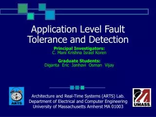
Application Level Fault Tolerance and Detection Principal Investigators: C. Mani Krishna Israel Koren Graduate Students: Diganta Eric Janhavi Osman Vijay Architecture and Real-Time Systems (ARTS) Lab. Department of Electrical and Computer Engineering University of Massachusetts Amherst MA 01003
What is ALFTD? • ApplicationLevelFaultTolerance andDetection • ALFTD complements existing system or algorithm level fault tolerance by leveraging information available only at the application level • Using such application level semantic information significantly reduces the overall cost providing fault tolerance • ALFTD may be used alone or to supplement other fault detection schemes • ALFTD is scalable • Error overhead can be traded off with invested time overhead for fault tolerance Application Level Fault Tolerance and Detection
ALFTD Overview • Application Level Fault Tolerance and Detection allows for system survival of both data and system (instruction/hardware) faults. • System faults cause a process to eventually cease functioning • Data faults cause a process to continue running with incorrect results • ALFTD has been implemented into OTIS to determine its feasibility as a fault detection and tolerance method for REE applications • OTIS has two sets of related output data, the temperature and emissivity • Experiments have focused mostly on the temperature output Application Level Fault Tolerance and Detection
OTIS Structure OUTPUT M MPI 1. MPI Starts S 2. MPI Starts Slave and master processes S 3. Master sends tasks S 5. Slave Output to File 4. Slave Calculations Application Level Fault Tolerance and Detection
OTIS’ Work Distribution • OTIS’ dynamic workload distribution allows it to compensate for system faults • Work originally partitioned for a failed processor is instead taken by the remaining processes • OTIS does not compensate for data faults • As long as the work is completed, there is no measure of correctness • OTIS does not consider deadline repercussions Application Level Fault Tolerance and Detection
OTIS Fault Cases Application Level Fault Tolerance and Detection
ALFTD OTIS Structure OUTPUT M ? MPI P1 1. MPI Starts S2 2. MPI Starts Slave and master processes, primary and secondary P2 S3 3. Master sends tasks P3 S1 4. Slave Calculations 5. Slave Output to File? Application Level Fault Tolerance and Detection
Secondaries in OTIS • The secondary required for ALFTD is implemented to be functionally similar to the primary • Secondary scaling occurs through resolution reduction • OTIS’ “natural” data input exhibits spatial locality • Points not directly calculated can be approximately estimated using interpolation between calculated points • Secondary processes have been tested at 20%-50% of the primary calculation overhead • While 50% affords better quality, 20% has less overhead Application Level Fault Tolerance and Detection
Example of Secondary Resolution (ALFTD Compensation for 10 rows in a sample dataset) 100% Secondary Resolution 50% Secondary Resolution 33% Secondary Resolution 25% Secondary Resolution Application Level Fault Tolerance and Detection
ALFTD Benefit Application Level Fault Tolerance and Detection
ALFTD Benefit (cont’d) Application Level Fault Tolerance and Detection
Fault Detection • When to run the secondary, and when to use the secondary output, is determined by output filters • Output filters are created to check for application-specific trends in data • Aberrations from normal data characteristics can be considered to be the product of potentially faulty processes • OTIS relies on natural temperature characteristics to detect potentially faulty data • Spatial Locality: temperature changes gradually over small areas • Absolute Bounds: temperature should not exceed certain values Application Level Fault Tolerance and Detection
Data Sets • Three data sets were chosen for their interesting characteristics Application Level Fault Tolerance and Detection
Data Frequency (Values) Application Level Fault Tolerance and Detection
Data Frequency (Spatial Locality) Application Level Fault Tolerance and Detection
Validation Through Secondaries • When the primary deadline is hit, rows are re-delegated to the secondaries if (and only if): • The primary has returned results for that row suspected to be faulty • The secondary results can be used to decide whether the results are indeed faulty • A particular row was never successfully calculated • The secondary results can be immediately used in place of the missing primary results Application Level Fault Tolerance and Detection
Validation Through Secondaries (cont’d) • After the secondary has been run to verify a primary’s results, the “better” data is chosen according to the following logic grid: Secondary Application Level Fault Tolerance and Detection
Fault Tolerance Results: “Spots” • Fault Tolerance with injected faults in “Spots” Application Level Fault Tolerance and Detection
Fault Tolerance Results: “Spots” (cont’d) Fault-Free Output Faulty Output 25% ALFTD Computation Overhead 33% ALFTD Computation Overhead 50% ALFTD Computation Overhead ALFTD-corrected faulty output Application Level Fault Tolerance and Detection
Fault Tolerance Results: “Spots” (cont’d) Difference Plots – faulty output versus faultless output No ALFTD 25% ALFTD Computation Overhead 33% ALFTD Computation Overhead 50% ALFTD Computation Overhead No Error Max Error Application Level Fault Tolerance and Detection
Fault Tolerance Results: “Blob” • Fault Tolerance with injected faults in “Blob” Application Level Fault Tolerance and Detection
Fault Tolerance Results: “Blob” (cont’d) Fault-Free Output Faulty Output 25% ALFTD Computation Overhead 33% ALFTD Computation Overhead 50% ALFTD Computation Overhead ALFTD-corrected faulty output Application Level Fault Tolerance and Detection
Fault Tolerance Results: “Blob” (cont’d) Difference Plots – faulty output versus faultless output No ALFTD 25% ALFTD Computation Overhead 33% ALFTD Computation Overhead 50% ALFTD Computation Overhead No Error Max Error Application Level Fault Tolerance and Detection
Fault Tolerance Results: “Stripe” • Fault Tolerance with injected faults in “Stripe” Application Level Fault Tolerance and Detection
Fault Tolerance Results: “Stripe”(cont’d) Fault-Free Output Faulty Output 25% ALFTD Computation Overhead 33% ALFTD Computation Overhead 50% ALFTD Computation Overhead ALFTD-corrected faulty output Application Level Fault Tolerance and Detection
Fault Tolerance Results: “Stripe”(cont’d) Difference Plots – faulty output versus faultless output No ALFTD 25% ALFTD Computation Overhead 33% ALFTD Computation Overhead 50% ALFTD Computation Overhead No Error Max Error Application Level Fault Tolerance and Detection
Emissivity Data • Emissivity is loosely proportional to temperature data • Emissivity exhibits spatial locality • Emissivity has natural bounds of expected data <0.5 - Faulty >1.0 - Faulty Natural Metal ~0.5 Rock ~0.8 - ~0.95 Vegetatation, Water ~1.0 Application Level Fault Tolerance and Detection
Emissivity Data (cont’d) • Emissivity does not exhibit the same data “closeness” as temperature output • This makes it very difficult to distinguish faulty from non-faulty data • Luckily, faults present in temperature output are easily detected, and reflect faults in emissivity output. • Emissivity does not have per-pixel independence of calculation • Dependence on the correctness of neighboring pixels makes resolution reduction a viable, but not the best, method for secondary reduction Application Level Fault Tolerance and Detection
Data Frequency (Emissivity Values) Application Level Fault Tolerance and Detection
Conclusion • ALFTD has already shown to be a worthwhile alternative to full redundancy • Improvements on the scheme will increase fault coverage and decrease secondary calculation overhead in both the emissivity and temperature outputs • OTIS, as a general matrix-based, master/slave program is a springboard to other, similar programs (e.g., NGST) • ALFTD as a fault-detection scheme will continue to be effective in programs which exhibit “natural” output Application Level Fault Tolerance and Detection
Thank You! Application Level Fault Tolerance and Detection
Relative Error Calculation • Error in OTIS output is calculated relative to a faultless “template” • The average relative error is the average of all relative errors of the entire output • Faulty value = f(x,y) • Faultless value = F(x,y) • Error = Application Level Fault Tolerance and Detection