Download
1 / 51
560 likes | 743 Views
Electromagnetic Induction. emf is induced in a conductor placed in a magnetic field whenever there is a change in magnetic field. Faraday’s work. Faraday suggested that an e.m.f. is induced in a conductor when 1. there is a change in the number of lines ‘linking’ it ,

E N D
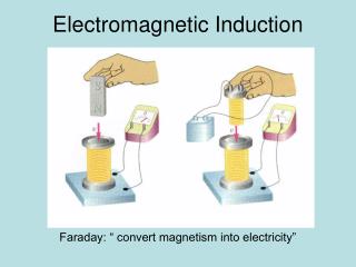
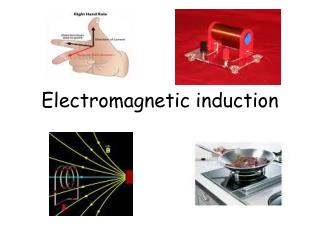
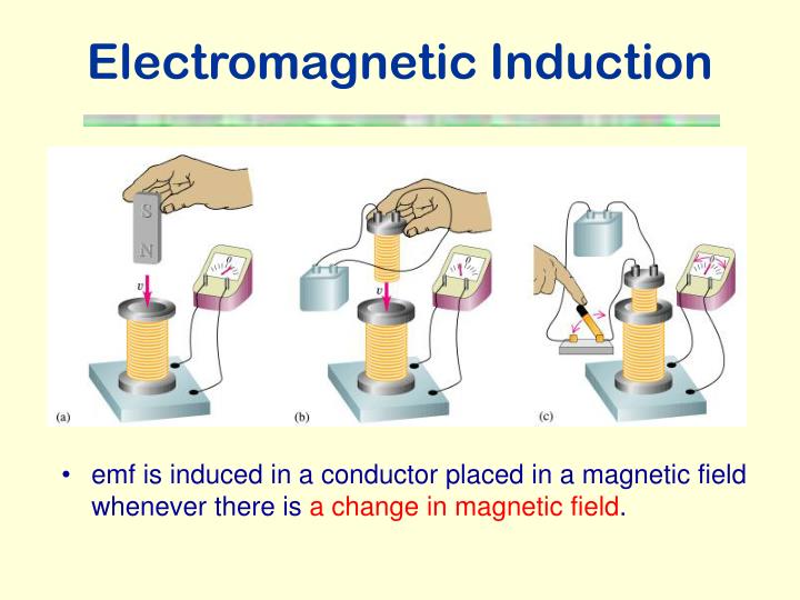
Electromagnetic Induction • emf is induced in a conductor placed in a magnetic field whenever there is a change in magnetic field.
Faraday’s work • Faraday suggested that an e.m.f. is induced in a conductor when 1. there is a change in the number of lines ‘linking’ it, 2. it ‘cuts’ across field lines.
As shown in the figure, if the coil moves towards the magnet from X to Y, the number of magnetic field lines linking itincreases from three to five; alternatively we can say it cuts two lines in moving from X to Y. • Hence, an e.m.f. is induced in the coil.
The figure shows two stationary coils A and B. • When a current flowing in coil A increases or decreases, the magnetic flux linking coil B increases and decreases respectively. Hence, an e.m.f. is induced in coil B.
x x x x x x x x x x x x x x x x x x x x x x x x x x x x A B Magnetic flux • B: magnetic flux density (i.e. the number of magnetic field lines per unit cross-section area) • A: cross-section area, • magnetic flux linking the area is the product BA represents the number of field lines linking a surface of cross-sectional area A. • = BA • If B = 1 T and A = 1 m2, F is defined to be 1 (Tm2) or weber (Wb).
Normal B = BA = BA cos q q B B-field ⊥ plane of coil Magnetic flux • If the surface is not perpendicular to the field with the normal to the surface making an angle q to the field, the magnetic flux linking the area is = BA cos q. • If F is the flux through the cross-section area A of a coil of N turns, the total flux through it, called the flux-linkage, is NF since the same flux F links each of the N turns.
Example 1 • A circular coil of 20 turns with diameter 10 cm is placed in a region of uniform magnetic field of 1.5 T. Find the flux-linkage if the plane of the coil • (a) is perpendicular to the field, • Solution:
Example 1 • A circular coil of 20 turns with diameter 10 cm is placed in a region of uniform magnetic field of 1.5 T. Find the flux-linkage if the plane of the coil • (b) is along the field, and • Solution:
Example 1 • A circular coil of 20 turns with diameter 10 cm is placed in a region of uniform magnetic field of 1.5 T. Find the flux-linkage if the plane of the coil • (c) makes an angle of 30o to the field. • Solution:
Faraday’s law The induced e.m.f. is directly proportional to the rate of change of flux-linkage or rate of flux cutting. • Mathematically, or . • It is defined that 1 Wb is magnetic flux that induces in a one-turn coil an e.m.f. of 1 volt when the flux is reduced to zero in 1 s. • By putting e = 1 V, dt = 1 s and d(NF) = 1 Wb, we have 1 = constant x 1/1. • Hence,
Example 2 • (a) Suppose a 5000-turn coil of cross-section area 5 cm2 is at right angles to a flux density of 0.2 T, which is then reduced steadily to zero in 10 s. Find the e.m.f. induced in the coil. • (b) Find the e.m.f. induced if the normal to the plane of coil makes an angle of 60o with the field. • Solution
Lenz's law Induced Ialways flows to oppose the movement which started it. In both cases, magnet moves against a force. Work is done during the motion & it is transferred as electrical energy.
Lenz’s law is incorporated in the mathematic expression of Faraday’s law by including a negative sign to show that current due to the induced e.m.f. produces an opposing flux change. So we have
Fleming's right-hand rule For a wire cutting through a B-field... motion or force F magnetic field B induced current I
observer Example 3 • State the direction of induced current flowing through coil B observed by the observer when the current through coil A increases steadily. • Solution:
l B v Calculation of e.m.f. • Consider a conducting rod of length l moving sideways with constant velocity v through and at right angles to a uniform magnetic field of flux density B. • Area swept out per second by the rod per second = lv • Flux cut per second = Blv • e.m.f induced = rate of flux-cutting = flux cut per second e = Blv
Alternative derivation • Magnetic force = Bqv. • An electric field is built up due to the accumulation of charges. • Electric force = qE • Finally, equilibrium is reached when magnetic force acting on electrons is balanced by electric force. • Hence, qE = Bqv⇒ E = Bv • An e.m.f. e is generated across the conductor such that e = El = Blv.
Example 4 • A metal aircraft of wing span l = 32 m is flying with speed v = 190 ms-1 towards the earth’s magnetic north pole in a region where the earth’s magnetic field BR = 4.3 x 10⁻⁵ T and the angle of dip a = 65o. • Calculate the e.m.f. induced across its wing tips. • Solution:
Simple a.c. Generator • According to the Faraday’s law of electromagnetic induction, http://www.walter-fendt.de/ph11e/generator_e.htm
Back e.m.f. Sparks appear while opening a switch • There is current flowing in the coil of the electromagnet in use. • When the circuit is broken by opening the switch, the current starts to drop and the flux linkage through the coil of the electromagnet decreases suddenly. • By Faraday’s law, a large induced e.m.f. would develop across the coil of the electromagnet so as to oppose the change. • Sparks occur due to the discharge across the small gap of the switch.
DC motors • A d.c. motor consists of a coil on an axle, carrying a d.c. current in a magnetic field. • The coil experiences a couple as in a moving-coil galvanometer which makes it rotate. • When its plane is perpendicular to the field, a split-ring commutator reverses the current in the coil and ensures that the couple continues to act in the same direction thereby maintaining the rotation.
Back emf in Motors • When an electric motor is running, its armature windings are cutting through the magnetic field of the stator. Thus the motor is acting also as a generator. • According to Lenz's Law, the induced voltage in the armature will oppose the applied voltage in the stator. • This induced voltage is called back emf.
Armature coils, R Back emf, Eb Driving source, V Back emf and Power • So the mechanical power developed in motor MultiplyingbyI, then
I t 0 Variation of current as a motor is started • As the coil rotates, the angular speed as well as the back emf increases and the current decreases until the motor reaches a steady state. Larger load Zero load
The need for a starting resistance in a motor • When the motor is first switched on, =0. • The initial current, Io=V/R, very large if R is small. • When the motor is running, the back emf increases, so the current decrease to its working value. • To prevent the armature burning out under a high starting current, it is placed in series with a rheostat, whose resistance is decreases as the motor gathers speed.
I 0 Variation of current with the steady angular speed of the coil in a motor • The maximum speed of the motor occurs when the current in the motor is zero.
Eddy Current • An eddy current is a swirling current set up in a conductor in response to a changing magnetic field. • When the magnetic flux linkage through a conductor changes, an e.m.f. is induced in it. • If the conductor is a lump of metal. These are known as Eddy Currents. • Eddy currents may be quite large because of the low resistance of the paths they follow.
Consider a metallic sheet moving away from a magnetic field. • By Lenz’s law, eddy currents must flow in a direction to oppose the motion of the sheet. • Hence, eddy currents act as an effective brake to its motion. • The mechanical work done is converted into internal energy of the sheet.
Applications1 Smooth Braking Device • The eddy currents induced in the copper plate produce a strong braking effect on the plate which stops oscillating quickly. • If the copper plate is replaced by one with slits, the induced eddy currents, which can only flow within the narrow teeth between the slits, are greatly reduced. This is because the resistance of the path which the eddy currents follow is increased.
pointer eddy currents soft-iron core Braking effect in moving-coil galvanometer • As the core swings in a magnetic field, eddy currents are induced in it. Since the eddy currents flow in a direction to oppose the motion, unwanted oscillations are reduced.
Ideal design of the core is to produce critical damping in which oscillation is just avoided.
Metal Detector • A pulsing current is applied to the coil, which then induces a magnetic field shown in blue. When the magnetic field of the coil moves across metal, such as the coin in this illustration, the field induces electric currents (called eddy currents) in the coin. • The eddy currents induce their own magnetic field, shown in red, which generates an opposite current in the coil, which induces a signal indicating the presence of metal. • A metal detector can also be used to detect mines buried underground.
Induction cooker • The induction cooker uses coils of wire with high frequency a.c. to produce large eddy currents in the metal cooking pot placing above. The heating effect of the eddy current cooks the food. • Moreover, since eddy current is not induced in its plastic case which is made up of non-metallic material, the cooker is not hot to touch.
Transformer • A transformer is a device for stepping up or down an alternating voltage. • For an ideal transformer, • (i.e. zero resistance and no flux leakage)
Transformer Energy Losses • Heat Losses • Copper losses- Heating effect occurs in the copper coils by the current in them. • Eddy current losses- Induced eddy currents flow in the soft iron core due to the flux changes in the metal. • Magnetic Losses • Hysteresis losses- The core dissipates energy on repeated magnetization. • Flux leakage- Some magnetic flux does not pass through the iron core.
Designing a transformer to reduce power losses • Thick copper wire of low resistance is used to reduce the heating effect (I2R). • The iron core is laminated, the high resistance between the laminations reduces the eddy currents as well as the heat produced. • The core is made of very soft iron, which is very easily magnetized and demagnetized. • The core is designed for maximum linkage, common method is to wind the secondary coil on the top of the primary coil and the iron core must always form a closed loop of iron.
Transmission of Electrical Energy • Wires must have a low resistance to reduce power loss. • Electrical power must be transmitted at low currents to reduce power loss. • To carry the same power at low current we must use a high voltage. • To step up to a high voltage at the beginning of a transmission line and to step down to a low voltage again at the end we need transformers.
Direct Current Transmission • Advantages • a.c. produces alternating magnetic field which induces current in nearby wires and so reduce transmitted power; this is absent in d.c. • It is possible to transmit d.c. at a higher average voltage than a.c. since for d.c., the rms value equals the peak; and breakdown of insulation or of air is determined by the peak voltage. • Disadvantage • Changing voltage with d.c. is more difficult and expensive.
Self Induction • When a changing current passes through a coil or solenoid, a changing magnetic flux is produced inside the coil, and this in turn induces an emf. • This emf opposes the change in flux and is called self-induced emf. • The self-induced emf will be against the current if it is increasing. • This phenomenon is called self-induction.
Definitions of Self-inductance (1) • Definition used to find L The magnetic flux linkage in a coil the current flowing through the coil. Where L is the constant of proportionality for the coil. L is numerically equal to the flux linkage of a circuit when unit current flows through it. Unit : Wb A-1 or H (henry)
Definitions of Self-inductance (2) • Definition that describes the behaviour of an inductor in a circuit Lis numerically equal to the emf induced in the circuit when the current changes at the rate of 1 A in each second.
Inductors • Coils designed to produce large self-induced emfs are called inductors (or chokes). • In d.c. circuit, they are used to slow the growth of current. • Circuit symbol or
Inductance of a Solenoid • Since the magnetic flux density due to a solenoid is • By the Faraday’s law of electromagnetic induction,
Energy Stored in an Inductor • The work done against the back emf in bringing the current from zero to a steady value Io is
Current growth in an RL circuit • At t = 0, the current is zero. • So • As the current grows, the p.d. across the resistor increases. So the self-induced emf ( - IR) falls; hence the rate of growth of current falls. • As t
Decay of Current through an Inductor • Time constant for RL circuit • The time constant is the time for current to decrease to 1/e of its original value. • The time constant is a measure of how quickly the current grows or decays.
- + emf across contacts at break • To prevent sparking at the contacts of a switch in an inductive circuit, a capacitor is often connected across the switch. The energy originally stored in the magnetic field of the coil is now stored in the electric field of the capacitor.
- + Switch Design • An example of using a protection diode with a relay coil. • A blocking diode parallel to the inductive coil is used to reduce the high back emf present across the contacts when the switch opens.