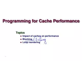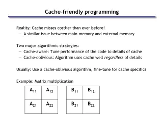
Cache Oblivious Programming: The Story So Far
Explore cache optimizations for array programs: cache-aware vs cache-oblivious approaches, loop interchanges, tiling techniques, lessons from Goto BLAS, implementation insights, and performance trade-offs. Understand the impact on memory traffic, control structures, block computations, and data structures. Discover how cache-conscious algorithms like register blocking can boost performance, with practical examples and considerations. Dive into the nuances of cache optimization at different memory hierarchy levels and how it influences program efficiency. Join us on a journey through cache management strategies and their implications on computational tasks.


Cache Oblivious Programming: The Story So Far
E N D
Presentation Transcript
Story so far • We have studied cache optimizations for array programs • Main transformations: loop interchange, loop tiling • Loop tiling converts matrix computations into block matrix computations • Need to tile for multiple memory hierarchy levels • At least registers and L1/L2 • Interactions between blocking at different levels is complex (main lesson from Goto BLAS) • Code becomes very complex: hard to write and maintain • Blocked code has parameters that depend on machine • Code is not portable, although ATLAS shows how to get around this problem
Cache-oblivious approach • Very different approach to optimizing programs for caches • Basic idea: • Use recursive algorithms • Divide-and-conquer process produces sub-problems of smaller sizes automatically • Can be viewed as approximate blocking • Many more levels of blocking than memory hierarchy levels • Block sizes are not optimized for cache capacities • Famous result of Hong and Kung • Recursive algorithms for matrix-multiplication, transpose and FFT are I/O optimal • Memory traffic between cache levels is optimal to within constant factors with respect to any other order of performing same computations
Organization of lecture • CO and CC approaches to blocking • control structures • data structures • Why CO might work • non-standard view of blocking • Experimental results • UltraSPARC IIIi • Itanium • Xeon • Power 5 • Lessons and ongoing work
Blocking Implementations • Control structure • What are the block computations? • In what order are they performed? • How is this order generated? • Data structure • Non-standard storage orders to match control structure
C00 = A00*B00 + A01*B10 C01 = A01*B11 + A00*B01 C11 = A11*B01 + A10*B01 C10 = A10*B00 + A11*B10 Divide all dimensions (AD) 8-way recursive tree down to 1x1 blocks Gray-code order promotes reuse Bilardi, et. al. B00 B01 B B10 B11 A00 A01 C00 C01 A0 C0 A10 A11 C10 C11 A1 C1 Cache-Oblivious Algorithms C0 = A0*B C1 = A1*B C11 = A11*B01 + A10*B01 C10 = A10*B00 + A11*B10 • Divide largest dimension (LD) • Two-way recursive tree down to 1x1 blocks • Frigo, Leiserson, et. al.
CO: recursive micro-kernel • Internal nodes of recursion tree are recursive overhead; roughly • 100 cycles on Itanium-2 • 360 cycles on UltraSPARC IIIi • Large overhead: for LD, roughly one internal node per leaf node • Solution: • Micro-kernel: code obtained by unrolling recursive tree for some fixed size problem (RUxRUxRU) • Schedule operations in micro-kernel to optimize for processor pipeline • Cut off recursion when sub-problem size becomes equal to micro-kernel size, and invoke micro-kernel • Overhead of internal node is amortized over micro-kernel, rather than a single multiply-add. recursive micro-kernel
CO: Discussion • Block sizes • Generated dynamically at each level in the recursive call tree • Our experience • Performance of micro-kernel is critical • For a given micro-kernel, performance of LD and AD is similar • Use AD for the rest of the talk
Data Structures • Match data structure layout to access patterns • Improve • Spatial locality • Streaming Row-major Row-Block-Row Morton-Z
Data Structures: Discussion • Morton-Z • Matches recursive control structure better than RBR • Suggests better performance for CO • More complicated to implement • Use ideas from David Wise to reduce overhead • In our experience payoff is small or even negative sometimes • Bilardi et al report similar results • Use RBR for the rest of the talk
Cache-conscious algorithms Register blocking Cache blocking
CC algorithms: discussion • Iterative codes • Nested loops • Implementation of blocking • Cache blocking • Mini-kernel: in ATLAS, multiply NBxNB blocks • Choose NB so NB2 + NB + 1 <= CL1 • Compiler transformation: loop tiling • Register blocking • Micro-kernel: in ATLAS, multiply MUx1 block of A with 1xNU block of B into MUxNU block of C • Choose MU,NU so that MU + NU +MU*NU <= NR • Compiler transformation: loop tiling, unrolling and scalarization
Blocking • Microscopic view • Blocking reduces expected latency of memory access • Macroscopic view • Memory hierarchy can be ignored if • memory has enough bandwidth to feed processor • data can be pre-fetched to hide memory latency • Blocking reduces bandwidth needed from memory • Useful to consider macroscopic view in more detail
Example: MMM on Itanium 2 • Processor features • 2 FMAs per cycle • 126 effective FP registers • Basic MMM for (int i = 0; i < N; i++) for (int j = 0; j < N; j++) for (int k = 0; k < N; k++) C[i, j] += A[i, k] * B[k, j]; • Execution requirements • N3 multiply-adds • Ideal execution time = N3 / 2 cycles • 3 N3 loads + N3 stores = 4 N3 memory operations • Bandwidth requirements • 4 N3 / (N3 / 2) = 8 doubles / cycle • Memory cannot sustain this bandwidth but register file can
CPU Cache Memory Reduce Bandwidth by Blocking • Square blocks: NB x NB x NB • working set must fit in cache • size of working set depends on schedule • at most 3NB2 • Data movement in block computation = 4 NB2 • Total data movement = (N / NB)3 * 4 NB2= 4 N3 / NB doubles • Ideal execution time = N3 / 2 cycles • Required bandwidth from memory = (4 N3 / NB) / (N3 / 2) = 8 / NB doubles per cycle • General picture for multi-level memory hierarchy • Bandwidth required between level L+1 and level L = 8 / NBL • Constraints on NBL • Lower bound: 8 / NBL ≤ Bandwidth(L,L+1) • Upper bound: Working set of block computation ≤ Capacity(L)
4* ≥6 4 FPU Registers L1 L2 L3 Memory ≈0.5 ≥2 4 2* Example: MMM on Itanium 2 * Bandwidth in doubles per cycle; Limit 4 accesses per cycle between registers and L2 • Between Register File and L2 • Constraints • 8 / NBR ≤ 4 • 3 * NBR2 ≤ 126 • Therefore Bandwidth(R,L2) is enough for 2 ≤ NBR ≤ 6 • NBR = 2 required 8 / NBR = 4 doubles per cycle from L2 • NBR = 6 required 8 / NBR = 1.33 doubles per cycle from L2 • NBR > 6 possible with better scheduling
4* ≥6 4 FPU Registers L1 L2 L3 Memory ≈0.5 ≥2 4 2* Example: MMM on Itanium 2 * Bandwidth in doubles per cycle; Limit 4 accesses per cycle between registers and L2 • Between L2 and L3 • Sufficient bandwidth without blocking at L2 • Therefore L2 has enough bandwidth for 2 ≤ NBR ≤ 6 d 2 ≤ NBR ≤ 6 1.33 ≤ B(R,L2) ≤ 4 2 ≤ NBR ≤ 6 1.33 ≤ B(R,L2) ≤ 4
4* ≥6 4 FPU Registers L1 L2 L3 Memory ≈0.5 ≥2 4 2* Example: MMM on Itanium 2 * Bandwidth in doubles per cycle; Limit 4 accesses per cycle between registers and L2 • Between L3 and Memory • Constraints • 8 / NBL3 ≤ 0.5 • 3 * NBL32 ≤ 524288 (4MB) • Therefore Memory has enough bandwidth for 16 ≤ NBL3 ≤ 418 • NBL3 = 16 required 8 / NBL3 = 0.5 doubles per cycle from Memory • NBL3 = 418 required 8 / NBR≈ 0.02 doubles per cycle from Memory • NBL3 > 418 possible with better scheduling 2 ≤ NBL2 ≤ 6 1.33 ≤ B(L2,L3) ≤ 4 16 ≤ NBL3 ≤ 418 0.02 ≤ B(L3,Memory) ≤ 0.5 2 ≤ NBR ≤ 6 1.33 ≤ B(R,L2) ≤ 4
Lessons • Blocking can be useful to reduce bandwidth requirements • Block size does not have to be exact • enough for block size to lie within an interval that depends on hardware parameters • approximate blocking may be OK • Latency • use pre-fetching to reduce expected latency • So CO approach might work well • How well does it actually do in practice?
Organization of talk • Non-standard view of blocking • reduce bandwidth required from memory • CO and CC approaches to blocking • control structures • data structures • Experimental results • UltraSPARC IIIi • Itanium • Xeon • Power 5 • Lessons and ongoing work
UltraSPARC IIIi • Peak performance: 2 GFlops (1 GHZ, 2 FPUs) • Memory hierarchy: • Registers: 32 • L1 data cache: 64KB, 4-way • L2 data cache: 1MB, 4-way • Compilers • C: SUN C 5.5
Outer Control Structure Iterative Recursive Inner Control Structure Statement Naïve algorithms • Recursive: • down to 1 x 1 x 1 • 360 cycles overhead for each MA = 6 MFlops • Iterative: • triply nested loop • little overhead • Both give roughly the same performance • Vendor BLAS and ATLAS: • 1750 MFlops
Miss ratios • Misses/FMA for iterative code is roughly 2 • Misses/FMA for recursive code is 0.002 • Practical manifestation of theoretical I/O • optimality results for recursive code • However, two competing factors affect • performance: • cache misses • overhead • 6 MFlops is a long way from 1750 MFlops!
Outer Control Structure Iterative Recursive Inner Control Structure Statement Recursive Micro-Kernel None / Compiler Recursive micro-kernel(i) • Recursion down to RU • Micro-Kernel: • Unfold completely below RU to get a basic block • Compile using native compiler • Best performance for RU =12 • Compiler unable to use registers • Unfolding reduces recursive overhead • limited by I-cache
Outer Control Structure Iterative Recursive Inner Control Structure Statement Recursive Micro-Kernel None / Compiler Scalarized / Compiler Recursive micro-kernel(ii) • Recursion down to RU • Micro-Kernel • Scalarize all array references in the basic block • Compile with native compiler • In isolation, best performance for RU=4
Outer Control Structure Iterative Recursive Inner Control Structure Statement Recursive Micro-Kernel None / Compiler Scalarized / Compiler Belady / BRILA Coloring / BRILA Recursive micro-kernel(iv) • Recursion down to RU(=8) • Unfold completely below RU to get a basic block • Micro-Kernel • Scheduling and register allocation using heuristics for large basic blocks in BRILA compiler
Recursive micro-kernels in isolation Percentage of peak RU
Lessons • Register allocation and scheduling in recursive micro-kernel: • Integrated register allocation and scheduling performs better than Belady + scheduling • Intuition: • Belady tries to minimize the number of load operations for a given schedule • Minimizing load operations = minimizing stall cycles • if loads can be overlapped with each other, or with computations, doing more loads may not hurt performance • Bottom-line on UltraSPARC: • Peak: 2 GFlops • ATLAS: 1.75 GFlops • Optimized CO strategy: 700 MFlops • Similar results on other machines: • Best CO performance on Itanium: roughly 2/3 of peak
Outer Control Structure Iterative Recursive Inner Control Structure Statement Recursive Iterative Micro-Kernel None / Compiler Scalarized / Compiler Belady / BRILA Coloring / BRILA Recursion + Iterative micro-kernel • Recursion down to MU x NU x KU (4x4x120) • Micro-Kernel • Completely unroll MU x NU nested loop as in ATLAS
Iterative micro-kernel Register blocking Cache blocking
Lessons • Two hardware constraints on size of micro-kernels: • I-cache limits amount of unrolling • Number of registers • Iterative micro-kernel: three degrees of freedom (MU,NU,KU) • Choose MU and NU to optimize register usage • Choose KU unrolling to fit into I-cache • Recursive micro-kernel: one degree of freedom (RU) • But even if you choose rectangular tiles, all three degrees of freedom are tied to both hardware constraints
Loop + iterative micro-kernel • Wrapping a loop around highly optimized • iterative micro-kernel does not give good • performance • This version does not block for any cache • level, so micro-kernel is starved for data. • Recursive outer structure version is able to • block approximately for L1 cache and higher, • so micro-kernel is not starved. • What happens if we block explicitly for L1 cache • (iterative mini-kernel)?
Outer Control Structure Iterative Recursive Inner Control Structure Statement Recursive Iterative Mini-Kernel Micro-Kernel None / Compiler Scalarized / Compiler Belady / BRILA Coloring / BRILA Recursion + mini-kernel • Recursion down to NB • Mini-Kernel • NB x NB x NB triply nested loop (NB=120) • Tiling for L1 cache • Body of mini-kernel is iterative micro-kernel
Loop + iterative mini-kernel • Mini-kernel tiles for L1 cache. • On this machine, L1 tiling is adequate, so • further levels of tiling in recursive code do • not contribute to performance.
Outer Control Structure Iterative Recursive Inner Control Structure Statement Recursive Iterative Mini-Kernel Micro-Kernel ATLAS CGw/S ATLAS Unleashed None / Compiler Scalarized / Compiler Belady / BRILA Coloring / BRILA Recursion + ATLAS mini-kernel • Using mini-kernel from • ATLAS Unleashed gives • big performance boost over • BRILA mini-kernel. • Reason: pre-fetching • Mini-kernel from ATLAS • CGw/S gives same • performance as • BRILA mini-kernel.
Lessons • Vendor BLAS and ATLAS Unleashed get highest performance • Pre-fetching boosts performance by roughly 40% • Iterative code: pre-fetching is well-understood • Recursive code: not well-understood
Out-of-place Transpose • No data reuse, only spatial locality • Data stored in RBR format • Micro-kernels permit scheduling of • dependent loads and stores, so do • better than naïve code • Iterative micro-kernels do slightly • better than recursive micro-kernels
Summary • Iterative approach has been proven to work well in practice • Vendor BLAS, ATLAS, etc. • But requires a lot of work to produce code and tune parameters • Implementing a high-performance CO code is not easy • Careful attention to micro-kernel and mini-kernel is needed • Using fully recursive approach with highly optimized micro-kernel, we never got more than 2/3 of peak. • Issues with CO approach • Scheduling and code generation for micro-kernels: integrated register allocation and scheduling performs better than using Belady followed by scheduling • Recursive Micro-Kernels yield less performance than iterative ones using same scheduling techniques • Pre-fetching is needed to compete with best code: not well-understood in the context of CO codes