Download

1 / 27
980 likes | 2.83k Views
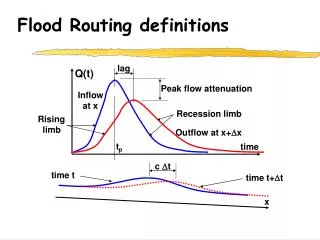
FLOOD ROUTING. ERT 246 Hydrology & Water Resources Eng. Q. t. Flow Routing. Q. t. Procedure to determine the flow hydrograph at a point on a watershed from a known hydrograph upstream As the hydrograph travels, it attenuates gets delayed. Q. t. Q. t. Why route flows?. Q. t.

E N D
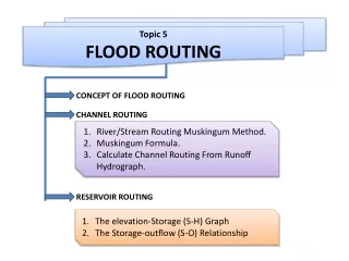
FLOOD ROUTING ERT 246 Hydrology & Water Resources Eng.
Q t Flow Routing Q t • Procedure to determine the flow hydrograph at a point on a watershed from a known hydrograph upstream • As the hydrograph travels, it • attenuates • gets delayed Q t Q t
Why route flows? Q t • Account for changes in flow hydrograph as a flood wave passes downstream • This helps in • Calculate for storages • Studying the attenuation of flood peaks
Types of flow routing • Lumped/hydrologic • Flow is calculated as a function of time alone at a particular location • Governed by continuity equation and flow/storage relationship • Distributed/hydraulic • Flow is calculated as a function of space and time throughout the system • Governed by continuity and momentum equations
Lumped flow routing • Three types • Level pool method (Modified Puls) • Storage is nonlinear function of Q • Muskingum method • Storage is linear function of I and Q • Series of reservoir models • Storage is linear function of Q and its time derivatives
Level pool routing • Procedure for calculating outflow hydrograph Q(t) from a reservoir with horizontal water surface, given its inflow hydrograph I(t) and storage-outflow relationship
Wedge and Prism Storage • Positive wedge I > Q • Maximum S when I = Q • Negative wedge I < Q
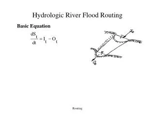
Hydrologic River Flood Routing Basic Equation
Wedge storage in reach Hydrologic river routing (Muskingum Method) Advancing Flood Wave I > Q K = travel time of peak through the reach X = weight on inflow versus outflow (0 ≤ X ≤ 0.5) X = 0 Reservoir, storage depends on outflow, no wedge X = 0.0 - 0.3 Natural stream Receding Flood Wave Q > I
_ _ - + + S S (I I ) (O O ) D S 2 1 1 2 1 2 = = - = - I O D - t t t 2 2 2 1 Continuity Equation in Difference Form • Referring to figure, the continuity equation in difference form can be expressed as
Derivation of Muskingum Routing Equation • By Muskingum Model, at t = t2, S2 = K [X I2 + (1 - X)O2] at t = t1, S1 = K [X I1 + (1 - X)O1] • Substituting S1, S2 into thecontinuity equation and after some algebraic manipulations, one has O2 = Co I2 + C1 I1 + C2 O1 • Replacing subscript 2 by t +1 and 1 by t, the Muskingum routing equation is Ot+1 = Co It+1 + C1 It + C2 Ot, for t = 1, 2, … where ; ; C2 = 1 – Co – C1 Note: K and t must have the same unit. Routing
Muskingum Routing Equation where C’s are functions of x, K, Dt and sum to 1.0
Muskingum Equations where C0 = (– Kx + 0.5Dt) / D C1 = (Kx + 0.5Dt) / D C2 = (K – Kx – 0.5Dt) / D D = (K – Kx + 0.5Dt) Repeat for Q3, Q4, Q5 and so on.
Estimating Muskingum Parameters, K and x Graphical Method: • Referring to the Muskingum Model, find X such that the plot of XIt+ (1-X)Ot (m3/s) vs St (m3/s.h) behaves almost nearly as a single value curve. The assume value of x lies between 0 and 0.3. • The corresponding slope is K.
Example 8.4: Estimating the value of x and K. • Try and error to get the nearly straight line graph.
Muskingum Routing Procedure • Given (knowns): O1; I1, I2, …; t; K; X • Find (unknowns): O2, O3, O4, … • Procedure: (a) Calculate Co, C1, and C2 (b) Apply Ot+1 = Co It+1 + C1 It + C2 Otstarting from t=1, 2, … recursively.
Example 8.5 • Given K and x. • Initial outflow, Q also given. Solution: Calculate Co, C1, and C2 C0 = (– Kx + 0.5Dt)/ D C1 = (Kx + 0.5Dt)/ D C2 = (K – Kx – 0.5Dt)/ D D = (K – Kx + 0.5Dt)
Solution: • Route the following flood hydrograph through a river reach for which K=12.0hr and X=0.20. At the start of the inflow flood, the outflow flood, the outflow discharge is 10 m3/s.
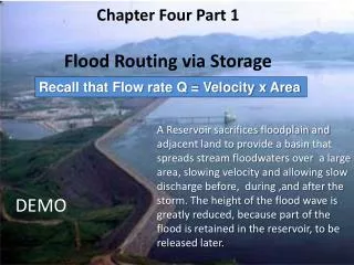
Reservoir Routing • Reservoir acts to store water and release through control structure later. • Inflow hydrograph • Outflow hydrograph • S - Q Relationship • Outflow peaks are reduced • Outflow timing is delayed Max Storage
Inflow and Outflow I1 + I2 – Q1 + Q2 S2 – S1 = 2 2 Dt
Inflow & Outflow Day 3 = change in storage / time Repeat for each day in progression
Determining Storage • Evaluate surface area at several different depths • Use available topographic maps or GIS based DEM sources (digital elevation map) • Outflow Q can be computed as function of depth for either pipes, orifices, or weirs or combinations
Typical Storage -Outflow • Plot of Storage in vs. Outflow in Storage is largely a function of topography • Outflows can be computed as function of elevation for either pipes or weirs Combined S Pipe Q
Comparisons: River vs. Reservoir Routing Levelpool reservoir River Reach
Flood Control • Structural Measures • Non-structural Methods