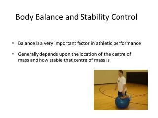
Stability and Control
Stability and Control. Stability. Planes and Axes There are terms to describe the movement of an aircraft in 3 dimensions. This is movement of the aircraft relative to itself- changes of it attitude- rather than it travelling through the air. 3 Planes of Movement.


Stability and Control
E N D
Presentation Transcript
Stability • Planes and Axes • There are terms to describe the movement of an aircraft in 3 dimensions. • This is movement of the aircraft relative to itself- changes of it attitude- rather than it travelling through the air.
3 Planes of Movement • There are three planes in which an aircraft moves. • Moves in the pitching plane (i.e. pitches) about its lateral axis • Moves in the rolling plane (i.e. rolls) about its longitudinal axis • Moves in the yawing plane (i.e. yaws ) about its normal axis
Why Stability? • If an aircraft experiences turbulence, a well-designed aircraft will tend to go back to level flight of its own accord, without a pilot having to make continual adjustments. • This property is called stability and to understand it we need to consider stability in each of the 3 planes.
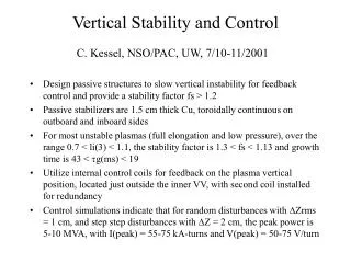
Stability in the Pitching Plane (Longitudinal Stability) If some disturbance jolts the aircraft into a tail-down attitude, the tail plane momentarily has an angle of attack to the oncoming air; consequently it produces lift which levers the aircraft back to level position
Stability in the Pitching Plane (Longitudinal Stability) If some disturbance jolts the aircraft into a nose-down attitude, the tail plane produces a downward force which levers the aircraft back into a level position. In this position the tail plane has no upward and downward force upon it
Stability in the Rolling Plane (Lateral Stability) • Most aircraft have wings which are set into the fuselage at a slight upward angle to the horizontal called the dihedral angle • This makes the aircraft laterally stable
If the wing drops in turbulent air, the lift force is no longer vertical and it no longer opposes the weight fully. Consequently, the aircraft begins to slip sideways, down towards the lower wing, and a side wind strikes it. Side wind
The lower wing, because of its dihedral angle, meets the side-wind at an angle- an angle of attack- which is greater than that of the upper wing. The lower wing therefore produces more lift than the upper wing and rolls the aircraft back until the wings are level Another reason is that the upper wing is shielded by the fuselage from some of the side-wind (airflow is slower) Side-wind
High wing aircraft • Another stable design is the high wing aircraft, where the centre of gravity is well below the wing: here, the pendulum effect of the weight of the aircraft gives lateral stability
Anhedral angle • Anhedral wings work on the same principle as dihedral, but with the opposite effect, creating lateral instability. This is the designer’s way of reducing the excessive lateral stability which can be encountered with ‘swept-back’ wings.
Stability in the Yawing Plane (Directional Stability) • If an aircraft is made to yaw to one side by an air disturbance, the side-wind blowing on its fuselage and fin surfaces creates a sideways force which, on areas to the rear of the centre of gravity, will tend to yaw the aircraft back to its original heading, just like a weather cock.
Of course, the sideways force on areas ahead of the centre of gravity will have the opposite (an unwanted) effect –which is why most aircraft have a fin, placed as far back as possible, to increase the weathercock effect and ensure directional stability.
How much Stability? • High stability can be extremely tiring as the pilot constantly has to overcome the stabilising forces. • Conversely, too little stability will mean that the pilot has to make continual corrections to keep the aircraft on the chosen flight path. • The designer must strike a balance • The amount of stability built into an aircraft depends on its role. • Higher for large aircraft, and least for fighters where good manoeuvrability is required
The Pilot’s Controls • The three main controls are: elevators, ailerons and rudder • Using these controls the pilot can make the aircraft: • A) Pitch – Where the nose of the aircraft rises (pitching up) or falls (pitching down) • B) Roll – When one wing rises while the other falls. Right wing down is rolling right. • C) Yaw- When the nose of the aircraft moves left (left yaw) or right (right yaw) • These are all relative to the pilot and not the horizon!!
Which way is ‘up’? • If the nose pitches towards the pilot’s head it is pitching up, and if it pitched towards the pilot’s feet it is pitching down. Similarly, when we say ‘left yaw’ or ‘right yaw’, ‘left roll’ or ‘right roll’, we are always referring to the pilot’s left and the pilot’s right, regardless of the attitude of the aircraft.
Elevators make the aircraft’s nose pitch nose-down or nose-up. The located on the tailplane and are hinged to the trailing edge where they have the most leverage. How The Pilot Uses The ControlsUse of Elevators
It is linked to the pilot’s control column (usually called the stick) Moving it forwards lowers the elevators and this levers the tail up/nose down about its lateral axis. How The Pilot Uses The ControlsUse of Elevators Elevators move up and down
In straight and level flight, the aircraft would dive Effect of Elevators
In a vertical climb, the aircraft would turn towards the level position. Effect of Elevators
Moving it backwards of course, has the opposite effect. ‘Stick Back, nose up’ But always remember that ‘up’ and ‘down’ are measured solely in relation to the pilot, and not to the world outside the aircraft. How The Pilot Uses The ControlsUse of Elevators Elevators move up and down
To roll the aircraft, the pilot uses the two moveable parts of the wings called the ailerons. They are linked to the stick and are located near the wing tips, where they have the most leverage about the centre of gravity The Rolling Plane Use of Ailerons
By moving the stick left, the pilot raises the left aileron and depressed the right. The left aileron thus has a reduced angle of attack and less lift. This rolls the aircraft to the left about its longitudinal axis Remember: Stick to the right, roll to the right Stick to the left, roll to the left
To move the aircraft in the yawing plane, the pilot uses the rudder, which is linked to the rudder pedals in the cockpit. The rudder is a single control surface which is hinged to the trailing edge of the fin. The Yawing PlaneUse of Rudder
The pilot’s feet rest on the rudder pedals during normal flight. To yaw to the left, the pilot pushes the left pedal forward, which makes the rudder move out to the left. The Yawing PlaneUse of Rudder
This produces a sideways force to the right. The tail is pushed sideways to the right, and the nose, of course to the left: the aircraft is now yawing to the left about its normal axis Left rudder, yaw to the left Right rudder, yaw to the right
What is Trimming? • Trimming tabs are used to ‘trim out’ (or cancel out) the forces on the stick or rudder which are created by alteration in power, speed or attitude or changes to the weight of the aircraft when fuel is used up, bombs dropped or ammunition fired. • No pilot could fly accurately or safely for long without some help from Trimming Tabs.
They are hinged in the trailing edges of the elevators, ailerons and rudder They can be moved at an angle to those surfaces by separate controls in the cockpit Where are Trimming Tabs?
If an aircraft has become nose heavy, a pilot would have to maintain steady backwards pressure on the stick. To trim out the constant backward force on the stick, the pilot operates the elevator trim control so as to depress the elevator trimming tabs downward into the air flow This produces lift which helps to hold the elevator up at the required angle This removes the need for a continuous force on the control column. How do Trimming Tabs Work? Holds Elevator up Trim tab down Aileron and rudder trimming tabs Operate on the same principle The aircraft is said to be trimmed longitudinally and will fly ‘hands off’
For the sake of safety, an aircraft’s wing should be designed so that the aircraft can make its approach to land at a controlled slow speed, and along a moderately steep approach path (so that they can see over the nose) A wing is designed largely for its main task, and flaps are used on the approach and landing. Location of flaps
Flaps are hinged surfaces along the trailing edges of the wings, in board of the ailerons. • The flaps are operated in stages by the pilot. • In the unused or ‘up’ position they lie flush with the wing surface and form part of the wing • In the fully down position they are at a angle of 90° or so to the wings surfaces
The many types of flaps all increase the effective camber of the wing and hence its lift In addition they will also increase drag Types of flaps
For most flaps there is a huge gain in lift when they are lowered to angles of 30° to 60°. For these angles drag increases only moderately. • It is now possible to use slower, safer approach and landing speeds. However, because of very little drag being produced, the approach angle is scarcely affected
If 90° of flap are selected this gives a tremendous increase in drag which in turn means that the pilot must lower the nose considerably to maintain the approach speed- in other words- the pilot has a much steeper approach angle and a better forward view. 15° of flap will also improve the lift at take-off speeds resulting in shortened take-off runs
Slat improve handling at low speeds. They are small aerofoils (shaped so as to develop lift), positioned along the leading edge of each wing Effect of slats on airflow
When slats are not needed they are held in the closed position by springs. At high angles of attack the slats open automatically and improve the airflow over the wing, with some beneficial effects. Instead of stalling at 15° or so, the wing can reach an angle of as much as 25° before stalling, and the stalling speed is reduced. They do, however, cause extra drag which is unwanted at high operating speeds- they then close automatically. Effect of slats on airflow
To provide maximum lift, so as to take off in the shortest possible distance, the leading edge slats are opened fully, and the flaps are extended to about 20° Inter-connected slat and flap Once the aircraft is airborne, the slats and flaps are closed