Download
1 / 31
310 likes | 396 Views
Conceptual Design of the Neutron Guide Holding Field. Christopher Crawford, Yunchang Shin University of Kentucky nEDM Collaboration Meeting 2009-06-19. Issues: constraints adiabaticity / abruptness field gradients. Design: DSCTC steel flux return taper in DSCTC. Outline.

E N D
Conceptual Design of the Neutron Guide Holding Field Christopher Crawford, Yunchang Shin University of Kentucky nEDM Collaboration Meeting 2009-06-19
Issues: constraints adiabaticity / abruptness field gradients Design: DSCTC steel flux return taper in DSCTC Outline -metal ext. 2m DSCTC 1010 steel flux return
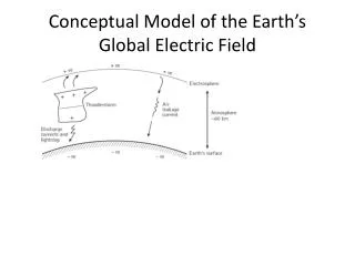
preserve neutron polarization (holding field) Larmor precession adiabatic – field uniformity abrupt – field smallness Majorana transitions ? avoid gradients in measurement cell from: holding field coils (left on) – field fringes magnetized Metglas (HF off) – field fringes magnetic material – no magnetic material spin dressing field uniformity – no conductors in B0 region neutron guide construction – no current sheets in guide SM polarizer – 300 G – 100 mG field taper Constraints
Issue – adiabaticity / abruptness • 100 mG doldrums • too large for abrupt changes • too low for adiabatic rotation in cryostat • could try and ‘steer’ spins into fringe with exit fringe either or both conditions will preserve polarization:
Field lines in double-cos-theta coil • require: B=0 outside B=B0 inside • solve M with Br boundary conditions • calculate j from Bt boundaryusing M • 1” flux return
Current windings on end face • Bt=0 on ends so solution is axially symmetric • equipotentials M=cform winding traces for current on face n£(H=rM) • end plates connect along inside/outside
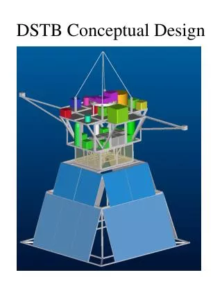
guide field ~ dipole directly affects B0 field if left on magnetizes Metglas if turned on and off repeatedly flux return ~ quadrupole magnetic material in cryostat distorts the field currents – DSCTC similar to dressing coil design arbitrary geometry inner coils – guide field outer coils – flux return end-caps – contain B-field current sheet omitted Issue – gradients Design – DSCTC
guide field should terminate at beginning of B0 field: conductors inside spin-dressing coils perturb RF field to match up and cancel out fringes don’t want current-sheet on end-cap of the DSCTC complicates neutron guide need to cancel B0 fringe quadrupole residual direct – gradient indirect – magnetization Issues – current sheet / spin dressing coils = +
Stray fields from DSCTC B(15cm, 15cm, 25cm) = (456,15.3, 149) x 10-8 G No Shields Shield & B0 (40 mG) dBx dBy dBz /dx 3.1 1.0 10. /dy 1.0 1.0 0.5 x10⁻⁸G/cm/dz 10. 0.5 4.1 dBx dBy dBz /dx 0.4 128? 0.8 /dy 0.1 0.1 0.2 x10⁻⁸G/cm/dz 0.9 0.2 0.7 Septimiu Balascuta
H. Yan, B. Hona, B. Plaster Lab Setup “quadrupole loops” deguassing coils triple-axis fluxgate magnetometer Nested Metglas shields: 1) 25.5” O.D., 67.5” long, 1.6 mils (2 layers) 2) 17.25” O.D., 48.5” long, 2.4 mils (3 layers)
Step #1: Quadrupoles off (baseline) Step #2: Quadrupoles on (impact) Step #3: Quadrupoles off (hysteresis) Bx(z) Bz(z) By(z) quadrupole at this end Note: x = vertical, y = horizontal
Step #1: Quadrupoles off (baseline) Step #2: Quadrupoles on (impact) Step #3: Quadrupoles off (hysteresis) Bx(x) Bz(x) Shapes ( gradients) similar Probably should be repeated for higher precision, test repeatability By(x) Results along y-axis are similar
Holding field downstream of bender • 5 G holding field in 10 m of guide downstream of bender • external 1010 steel yoke, 1/16” x 42.5 cm x 42.5 cm • 40 cm x 1 mm Al winding • 160 A-turns top and bottom • 92 /m, 4.7 W/m • coil vs. permanent magnets: • allows use of steel on all four sides of guide for both internal and external shielding • can be turned off during measurement cycle • low power • lightweight – 31 kg/m • mount on guide housing • horizontal vs. longitudinal field • double-cos-theta-coil transition • need same current as solenoidonly on top and bottom • each side can mount separately
External shielding • factor of 10 shielding of Earth’s magnetic field • By/Bx = 50 mG / 5 G • 0.57±perturbation of holding field angle • only matters at interface with double-cos-theta coil
Issue – field taper Top view beam right J y B z x beam left Side view guide top y J B z x guide bottom
Design – DSCTC taper 0 m – 100 mG 1 m – 189 mG 2 m – 460 mG 3 m – 2.4 G 4 m ~ 10 G 1.16 A 50 windings jmax =152 A/m Pmax =11.3W/m2 P~ 100 W
Design – DSCTC taper flux return lines
Extra Slides: B0 field alone / with DSCTC at x=12.5, y=12.5 cm (worst case)