Download
1 / 14
140 likes | 160 Views
Learn about cutting-edge developments in accelerator technologies and design strategies for developing Accelerator-Driven Systems (ADS) to optimize performance and reliability.

E N D
Linac for ADS Application - Accelerator Technologies Bob Garnett Accelerator Operations and Technology Division Los Alamos National Laboratory
OUTLINE ADS History ADS Requirements Accelerator Technologies
The ADS Accelerator Requirements are Unique – and Achievable • The ADS application drives the accelerator design to provide higher inherent reliability (beam on target). • The engineering challenges lie in the safe, controlled coupling of an accelerator to a sub-critical reactor through a spallation target. System control and safe operation will demand the understanding and resolution of the potentially complex behavior of this coupled accelerator/target/reactor system. The key to success will be how well the entire ADS system is integrated in design and operation.
Future 2% Beamstop Application Target/Blanket R=54.4m 17.1m 42.7 m 54 .4m 29.3m 1030.0 MeV 471.4 MeV 211.4 MeV R=27.2m 0.1% Beamstop 85.4m 298.9m 185.4m 235.1m Low-b SC Linac High- b SC Linac Section 2 Section 1 45.0m Medium- b SC Linac Work on the 1 GeV, 100 mA (100 MW) APT Accelerator and Target Provides the Design Basis for an ADS System Schematic of Tuning Beam Dump Two-cavity cryomodule isometric with shell cutaway. Photograph of LEDA RFQ Spoke cavities Photograph of LEDA H+ injector including LEBT (Low Energy Beam Transport)
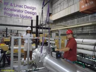
LEDA, the Low-Energy Demonstration Accelerator • Was funded by the APT program to demonstrate the technically challenging front end of a 1000-MeV, 100-mA proton accelerator. • Its operation from 1999-2001 demonstrated the success and feasibility of making this 100X jump in average beam current. • This same technology serves as the basis for APT, accelerator-driven waste transmutation, and other high-power accelerator uses. Energy: 6.7 MeV Current: 100 mA CW Beam Power: 0.67 MW RF Drive: 350-MHz klystrons
A Key to Success for ADS is Reducing Beam Interrupts - a New and Challenging Accelerator Requirement • Existing (LANSCE – linear accelerator, PSI - cyclotron) high-power accelerators have approximately 1 to 2 beam interrupts per hour of a 1 second or greater duration. • There are also an unknown number of very short beam interrupts; typically not logged if < 1 second duration. • In these machines, the design has given higher priority to equipment protection and overall availability than interrupt-free operation. • New linac designs (APT, SNS, and others) have emphasized high availability, but again, interrupt minimization has not been a requirement. • How to address this requirement will still require develop work.
Superconducting Structures Have Several Design Advantages – The Technology of Choice for ADS • Reduced Operating Cost (electricity, reduced linac length, etc.) • Operational Flexibility: • Large velocity acceptance of short multi-cell cavities. • Independent phasing of the cavities and independent control of amplitudes produces ability to continue operating even with some RF module failures (installed redundancy). Used Successfully at SNS. • Larger bore radius allows off-energy or poorly focused beams after faults to be transported to the target with minimal beam loss. • More Stable Operating Temperatures: • Reduced sensitivity to beam trips from thermally induced perturbations to cavity RF fields. • Improved Worldwide Industrial Capability: • There are now more commercial firms building SC than NC cavities and cryostats. Advances in superconducting technology makes its application very cost effective for this application.
The High Power Linac Requires Many Design Choices That Affect Reliability and Fault Handling • Design goals (Physics): • - Avoid beam envelope instabilities / resonances • - Achieve good beam capture • - Current-insensitive focusing lattice • - Efficient acceleration • - Reduce impact of beam interrupts – make choices that improve inherent insensitivity to faults. • Selection of accelerating gradients, synchronous phases, and beam-focusing lattice • Selection of these parameters affect modularity, etc. affecting reliability, availability, and maintenance of the cryomodules, RF systems, controls and diagnostics. (Engineering) • We used this approach in varying degrees for APT, ATW, ADS, and SNS.
A Different Design Approach May Be Needed to Meet ADS Accelerator Performance Requirements • Traditional / Historical Approach:- Low cost is a goal. • - Designed to meet technical performance requirements. • - Reliability, Availability, Maintainability (RAM) is a lower priority (improve as operational data becomes available). • Modern / Integrated Approach (A Goal?): • - Uses “lessons-learned” design principles (experience) to make the design inherently more fault tolerant, if possible. • - Use RAM analysis, Failure Mode and Effects analysis (FEMA), and physics modeling to improve fault handling. • - Should result in significant design optimization through iterative efforts. • 2-Stage Approach: • 1. Optimize the design for cost, technical performance and RAM. • 2. Design and implement appropriate monitoring systems to take care of everything else – Diagnostics and Controls.
A Basis for Using Reliability, Availability, and Maintainability Modeling in the Accelerator Design for ADS Exists • RAMI Model of the APT SC Linac High- Cryomodule • Original effort to develop an extensive model was done by Chris Piaszczyk (Grumman / AES) and Marcus Eriksson • (Royal Institute of Technology, Sweden). • Ongoing “Utilization and Reliability of High Power Proton Accelerators” Workshop Series, etc. • See for example: • Christopher M. Piaszczyk, “Accelerator Reliability Database,” Proceedings of the 1999 Particle Accelerator Conference, New York, 1999. • Eriksson M. and Piaszczyk C., “Reliability Assessment of the LANSCE Accelerator System,” • NEA/OECD Workshop on Utilization and Reliability of High Power Accelerators in Mito, • Japan, 13-15 Oct, 1998.
Baseline and Advanced SC Accelerator Design Concepts for Proton Linac for ADS b=0.64 5-cell cavity 350 MHz spokecavities 700 MHz5-cell ellipb=0.50 700 MHz5-cell ellipb=0.64 700 MHz5-cell ellipb=0.84 6.7 MeV b=0.12 130 MeV b=0.49 250 MeV b=0.61 1500 MeV b=0.79 As Part of the AAA Program, a b = 0.125, 5-Gap, 350 MHz Cavity was Developed 350 MHz5-cell spoke cavities 350 MHz spokecavities 1500 MeV 130 MeV 6.7 MeV • Replaces APT-like baseline with all-superconducting linac that could reduce cost and improve performance and reliability (i.e. beam continuity).- 4K Spoke cavities provide a higher temperature superconducting alternative to the 2K elliptical cavities.
Summary ADS was proposed to convert the 0.5% of the commercial spent fuel that requires ultra-long-term isolation into materials that are primarily stable or short-lived. Most likely: LWR waste will be the government’s problem – this is consistent with a large ADS machine collocated with a government reprocessing facility . • The objectives included: • Reducing isolation requirements to fit the lifetime of man-made containers and barriers. • Reducing incentives and consequences of intrusions into repositories. • Improving prospects for repositories and nuclear technologies. • Improving fuel utilization. • Making proliferation-resistant fuel streams. The major challenges in ADS are related to fuel forms and separations; the accelerator is based on significant past efforts and demonstrated technologies.
Separating Out and Storing the Pu, U, and Np Together Has Fuel Cycle Benefits • Am and Cm and their daughter nuclides are difficult to handle because of their high decay heat and radioactivity. • The low vapor pressure of americium limits fuel pellet fabrication temperatures. • In Fast Reactor accident scenarios the americium could boil out of the fuel and thus present a more difficult safety case. • Neptunium has similar chemical properties to uranium and plutonium and shows good compatibility not only in nitride fuel but also in oxide fuel. • Processing criticality issues are mitigated since the Pu is not separated out. • At worst same reprocessing cost but may be cheaper. • U/Pu/Np ratios are 98.7:1.2:0.1 making this a very unattractive material for diversion • Main issue with Actinide Reformer is flowing molten salt fuel requires active safety system to maintain keff<1
SMART Supports LWR Economy and Preserves U, Pu, & Np as a Future Resource Fuels and Targets Fabrication Light Water Reactor Uranium Pu/U/Np Storage SMART: Subcritical Minor Actinide Reduction through Transmutation Pu Pu Stores Pu source Am, Cm SMART Separations Facility Net 90% Operating Power Available MA & LLFP Tc and/or I targets* FP Stable & Short-Lived FPs, inc Ru, & Xe Stable & Short-Lived Fission Products Small Losses of TRU and Tc, I Waste Small Losses of TRU and Tc, I Waste Support ratio for a single burner end station = 20 * Tc and/or I may be incinerated in a separate burner Repository