Download
1 / 46
460 likes | 654 Views
Electric Charge. Electric current = a flow of electric charges. The electrons, which orbit the nucleus at relatively large distances can sometimes become free to move ? electric current.Electric charge is measured in coulombs (C)The charge on an electron = e = 1.6 x1

E N D
1. Current electricity � chap 21,22,23
2. Electric Charge Electric current = a flow of electric charges. The electrons, which orbit the nucleus at relatively large distances can sometimes become free to move ? electric current.
Electric charge is measured in coulombs (C)
The charge on an electron = e
= 1.6 x10⁻¹⁹C
3. Conductors and insulators Conductor � substance which allows electric current to flow through it
Insulator � substance which does not allow electric current to flow through it
4. Current Electric current (I)= amount of charge passing a point every second.
Measured in Amperes (A).
Measured using an ammeter, or for very small currents, a galvanometer
Current = Charge / time
I = Q / t
5. Conventional Current. Current = movement of electrons
Electrons move from negative to positive
However traditionally current was thought of as flowing from positive terminal of a battery to the negative (wrong way round)
We still use this convention today-current is thought of as flowing from positive to negative (conventional current)
6. DC and AC Two types of current exist
Direct current-always flows in the same direction � this is the type of current you get from a battery
Alternating current � here the current reverses direction many times per second-this is the type of current you get from the mains
7. Potential difference Water flows in a pipe if there is a height difference between the two ends-similarly current flows in a conductor if there is a potential difference between the two ends.
The potential difference between two points is defined as the energy lost by one coulomb as it moves from one point to the other- measured in volts.
1Volt = 1joule per coulomb
8. Definition of potential difference Since work = energy we can also define potential difference as
Potential difference = work done in bringing a unit charge from one point to the other
V = W / Q
9. Electrical power W = V Q
W / t = V Q/t
But Q/t = I
Thus W/t = VI
W/t = rate of doing work which is called the power
P = VI
10. Electromotive force (emf) EMF = the voltage between two ends of a circuit when no current is flowing in the circuit
11. Sources of EMF Electric cells-convert chemical energy to electrical energy
Consists of 2 different metals (the electrodes) immersed in a substance called an electrolyte.
A battery consists of a no. of cells connected together (a car battery = 6 2V cells in series)
12. Simple Cell Cu plate and Zn Plate in a beaker of dilute sulphuric acid
13. Primary and Secondary cells Primary cell = cell which cannot be recharged-once the chemicals are used up it must be discarded (e.g. dry battery)
Secondary cell = cell which can be recharged (usually by pushing current through it in the wrong direction) (e.g. car battery)
14. Ohm�s Law For a metallic conductor at constant temperature, the current flowing through the conductor is directly proportional to the p.d. across the conductor
V = constant I
The constant = resistance
V = I R
15. Resistance Electric currents (electrons) flow through conductors.
As they do so they collide with atoms in the conductor and so lose energy.
The material of the conductor RESISTS the current
16. If a conductor has a large resistance, then a large p.d. will only give a small current
If a conductor has a small resistance, then a large p.d. will give a large current
R = V / I
Resistance is measured in Ohms.
A conductor has resistance 1 O if the current through it is 1 amp when the p.d. = 1V
17. To measure resistance Two ways
1. using an ohmmeter
2. by measuring current and voltage and using the formula that V = I R
18. Experiment To demonstrate Ohm�s Law P258
19. Resistors Devices specially made to have a certain value of resistance
Can be either fixed or variable
Variable resistor-either a rheostat or a potentiometer � by moving the sliding contact you vary how much of the wire the current must pass through (i.e. the resistance)
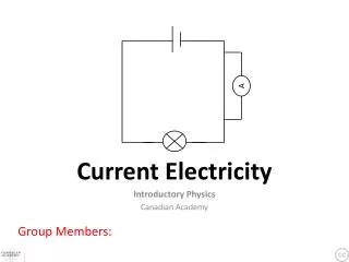
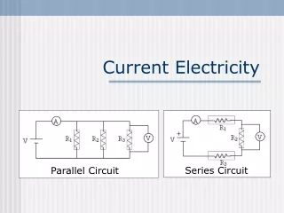
20. Connecting Circuits 2 ways to connect
Series
Parallel
21. Series Circuit Current has only one path ?
Itotal = I1 =I2 =I3
Voltages add
Vtotal = V1 +V2 +V3
From Ohm�s law V = I R?
Itotal Rtotal= I1R1 +I2R2 +I3R3?
Rtotal= R1 +R2 +R3
22. Parallel Circuit Current has several paths ?
Itotal = I1 +I2 +I3
Voltages stay the same
Vtotal = V1 =V2 =V3
From Ohm�s law V = I R?
Vtotal /Rtotal= V1/R1 +V2/R2 +V3/R3?
1/ Rtotal= 1/R1 +1/R2 +1/R3
Do questions p260
23. Kirchoff�s Laws The sum of the currents entering a junction = sum of the currents leaving the junction
The emf across the circuit = sum of the emfs across the individual parts of the circuit
24. Measuring current and voltage Currents are measured using an AMMETER which is placed in SERIES
Voltages are measured using a VOLTMETER which is placed in PARALLEL
25. Factors effecting resistance Resistance of a conductor depends on
Length of conductor (l)
Temperature of the conductor
The cross sectional area of the conductor
The material from which the conductor is made
26. Effect of temperature on resistance of a metal The resistance of a metal increases with increasing temp.
As the temperature of the metal increases the atoms of the metal vibrate more. This means that as the electrons try to pass through (electric current) they collide more and so lose energy ?resistance increases
27. Ctd. For moderate changes in temp. the change in resistance is proportional to the change in temp. �graph does not pass through the origin thus the resistance changes linearly with temperature (NOT directly proportional)
28. Effect of temperature on resistance of semiconductors or insulators In an insulator (or cold semiconductor) there are no electrons free to move and so no current.
As you heat the semiconductor some electrons break free of their bonds and so become free for conduction?the resistance decreases
29. Thermistor This is a semiconductor whose resistance decreases rapidly with increasing temp.
NOTE the relationship is not linear
30. Experiment To investigate the resistance of a metallic conductor with temp. P263
To investigate the resistance of a thermistor with temperature
P264
31. Other factors affecting resistance At constant temperature the resistance of a conductor depends on
Length
Cross-sectional area
The material from which the conductor is made
32. Experimentally it can be shown
R ? l
R ? 1/A
Thus R ? l / A
Thus R = constant l / A
This constant is called the resistivity (?) and depends on the material of the conductor
Thus R = ? l / A
33. often, we are measuring the resistance of wires. In these cases the cross sectional area is the area of a circle A = ?r2 where r = radius
Thus R = ? l / ?r2
Or, since r = d/2 (where d = diameter) R = ? 4l / ?d2
34. Resistivity (?) Defined as the resistance per unit length per unit cross sectional area
? = RA / l
Do questions p269
35. Experiment To measure the resistivity of the material of a wire
Use a micrometer screw gague to measure the diameter of the wire at several places, then take an average
Measure R using ohmmeter, or by measuring current and voltage
36. Wheatstone bridge A device for measuring the value of an unknown resistance
The values of the resistances are varied until no current flows through the galvanometer
37. At this point, the potential at B =potential at D (since no current flows)
Thus p.d. between A and B = p.d. between A and D (VAB=VAD)
Similarly VBC = VDC
From Ohm�s law V = IR
I1R1 = I2R3
I1R2 = I2R4
38. Thus
R1 / R2 = R3 / R4
Thus, if three of the resistors are known, you can calculate the value of the last.
Experimentally a resistor is placed in series with the galvanometer to protect it from too much current. This resistor is then removed when the aprox. balance point is found
39. Metre bridge This uses the same logic as the wheatstone bridge, but two of the resistors are replaced by a length of wire. A sliding contact divides the wire into two lengths, and so into 2 resistances. This makes it easier to adjust the resistance
40. The position of the sliding contact varies L1 and L2
41. We know from the wheatstone bridge circuit R1 / R2 = R3 / R4
In this case R3 and R4 are wires of uniform cross section (A) and the same material (? is the same)
Thus R3 =constant L1
R4 = constant L2
R1 / R2 =L1 / L2
42. Uses of wheatstone bridge circuits Temperature control � in this case the wheatstone bridge starts balanced. If the temperature of one of the resistors changes then its resistance will change, the bridge will no longer be balanced and so current flows through the galvanometer.
43. The size and direction of the current indicate the size and direction of the temperature change, and so can be used to control a heater and bring the temp. back to its original value
44. Fail-safe device � if the pilot light in a gas boiler goes out, you need the gas to shut off automatically.
A thermistor placed near the flame is used as one resistor in a wheatstone bridge. If the flame goes out the resistance increases, unbalances the bridge and current flows in the galvanometer. This current can be used to cut off the fuel
45. Potential divider circuit If two or more resistors are connected in series the total potential difference is divided between the resistors.
The bigger the resistor the bigger the potential across it (if one resistor is much bigger than the other effectively all the p.d. is across the big resistor)
46. Ctd. Such a system of resistors is known as a potential divider circuit-used when a smaller p.d. is required than the supply
47. Variable potential divider circuit Two resistors replaced by a variable resistor. The output voltage increases from O V when the contact is at A to the max input voltage when the contact is at B