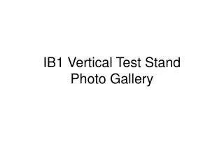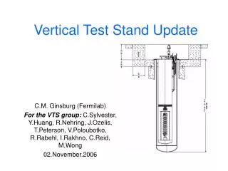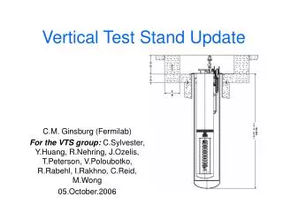
Vertical Test Stand
and its Upgrade Plan. R. Carcagno, C.M. Ginsburg , Y. Huang, R. Nehring, B. Norris, J. Ozelis, T. Peterson, V. Poloubotko, R. Rabehl, I. Rakhno, C. Reid, C. Sylvester, M. Wong, C. Worel. Vertical Test Stand. Test bare 1.3 GHz 9-cell superconducting RF cavities Measure Q vs. T

Vertical Test Stand
E N D
Presentation Transcript
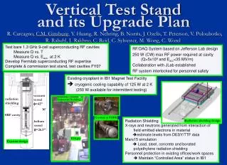
and its Upgrade Plan R. Carcagno, C.M. Ginsburg, Y. Huang, R. Nehring, B. Norris, J. Ozelis,T. Peterson, V. Poloubotko, R. Rabehl, I. Rakhno,C. Reid, C. Sylvester,M. Wong, C. Worel Vertical Test Stand Test bare 1.3 GHz 9-cell superconducting RF cavities Measure Q vs. T Measure Q vs. Eacc at 2 K Develop Fermilab superconducting RF expertise Complete & commission test stand, test cavities FY07 RF/DAQ System based on Jefferson Lab design 250 W (CW) max RF power required at cavity (Q>5x10⁹ and Eacc<35 MV/m) Collaboration with JLab established RF system interlocked for personnel safety Existing cryoplant in IB1 Magnet Test Facility cryogenic cooling capability of 125 W at 2 K (250 W available for intermittent testing) vacuum vessel f=42” radiation shielding Industrial Building 1 16’ SRF cavity Cryostat at PHPK Radiation Shielding X-rays and neutrons generated from interaction of field emitted electrons in material estimate levels from DESY/TTF data Mars15 simulation Lead, steel, concrete and borated polyethylene radiation shielding Personnel protection in existing offices/workspaces Maintain “Controlled Area” status in IB1 Radiation shielding design helium vessel f=26.5” VTS pit Cryostat design
Projected annual cavity tests Projected annual # cavity tests in US for ILC Upgrades • To increase Vertical Test throughput • Upgrade VTS for two-cavity operation • Add two more vertical test stands • Upgrade cryogenic infrastructure • To support cavity R&D, e.g., field emission studies and quench location IB1 cryogenic system infrastructure Black: existing/under construction Red: proposed upgrade Single VTS capacity expected ~ 48/year 3 vertical test stands and cavity staging area • Reduce schedule risk by adding safeguards to reduce downtime • Add compressor and purifier skid at vacuum pumps’ outlet to eliminate contamination from sub-atmospheric operation (primarily air-leaks) • Decouple vertical cavity testing from superconducting magnet tests • Install dedicated vacuum pump for cavity vertical tests to decouple from superfluid magnet tests • Add dedicated 10-ton crane for cavity test area • Add helium gas storage capacity and staff to accommodate three VTS cryostats • All upgrades require additional transformer