Download
1 / 9
90 likes | 170 Views
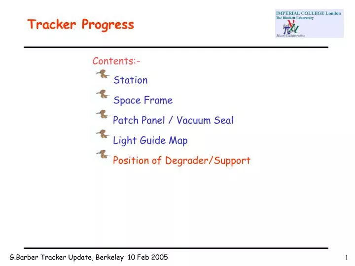
Tracker Progress. Contents:- Station Space Frame Patch Panel / Vacuum Seal Light Guide Map Position of Degrader/Support. Station. The bare carbon fibre station machined and ready to accept the scintillating fibre planes. Station ‘Connectorisation’.

E N D
Tracker Progress • Contents:- • Station • Space Frame • Patch Panel / Vacuum Seal • Light Guide Map • Position of Degrader/Support
Station The bare carbon fibre station machined and ready to accept the scintillating fibre planes.
Station ‘Connectorisation’ Each station has a total of 30 connectors, 10 per view. Each connector has 22 holes instead of the previous 18 but all of these are not used in every connector. All 3 planes are aligned and glued before the ‘connectorisation’ can begin. This is one of the main areas where a rigid QA system will need to be implemented. The photograph shows Roger Hare fitting connectors to the 4th prototype station at Imperial on Monday.
Space Frame Tooling The jigs that align the space frames are all manufactured. Components All of the components that make the space frame assemblies have been or are in the process of being manufactured. One further development?
Connector Map 126 Way 125 Way This is the connector map created for the KEK Test beam prototype. It will be updated for the final detector and will be a more uniform layout. View ‘W’ 211 Channels View ‘V’ 211 Channels View ‘X’ 211 Channels 128 Way 126 Way 128 Way
Connector 1 View ‘V’ 18 Way Bundles 2 – 19 To Bulkhead Connector - 1 2 6 5 3 4 11 10 9 7 8 12 17 16 15 13 14 x x 18 19 x x Station connector Viewed from the polished face
9 2 3 7 10 11 13 4 8 12 5 6 14 15 22 23 16 17 20 21 24 25 18 19 26 27 34 35 28 29 32 33 36 37 30 31 38 39 46 47 40 41 44 45 48 49 42 43 58 60 51 50 59 53 52 57 56 61 55 54 62 70 72 64 63 68 71 65 66 69 73 67 74 82 84 83 75 76 77 80 85 78 81 79 94 96 87 95 86 89 88 93 97 91 92 90 106 108 99 109 101 98 105 107 100 103 104 102 121 118 120 111 119 110 113 112 117 115 116 114 x x 123 125 127 122 124 126 Bulkhead Connector 1 View ‘V’ 126 Way Bundles 2 – 127 in ‘V’ From Connectors C1 – C6 Station connector Viewed from the polished face
Lead Diffuser The lead diffuser will sit inside the bore of the cryostat at a position of Z = -6015 This is 238mm from the tracker plane. It will be supported on a spider that is fixed to the patch panel and can be put into position in ‘thin slices’. This gives 2 advantages:- it can be put into position in manageable pieces (weight) and the thickness/position can easily be changed. Extended guide studs also give more security during the installation.
Conclusions There is still a great deal to design and detail and a few outstanding problems to solve but overall the design should be pretty much as for the prototype. So once the prototype is completed in the next few weeks and assuming we find no major problems with the construction philosophywe can then concentrate on the final detailed design.