Download
1 / 17
170 likes | 329 Views
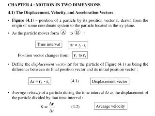
4. Microsystems in measurements of mechanical quantities- displacement, velocity and acceleration. Mechanical quantities important in measurements with sensors : x(t), (t), = x/x , - position (linear, angular), displacement, elongation (strain)

E N D
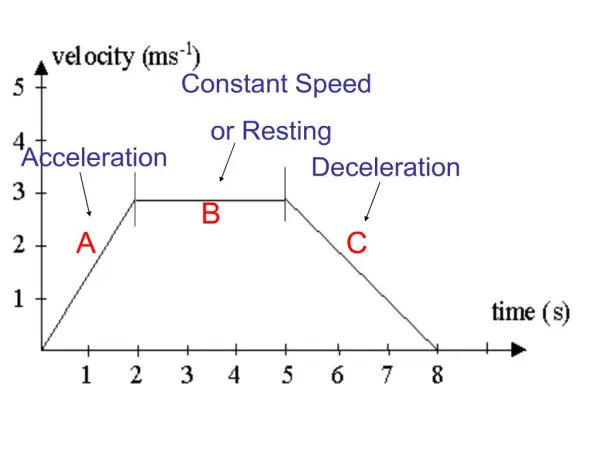
4. Microsystems in measurements of mechanical quantities- displacement, velocity and acceleration Mechanical quantities important in measurements with sensors: • x(t), (t), = x/x , - position (linear, angular), displacement, elongation (strain) • v = dx/dt, = d/dt, a = dv/dt– velocity, acceleration (linear, angular) • F = ma, = dF/dA, M = F d - force, pressure, torque dm/dt, dV/dt - mass flow, volume flow For quantities varying in time we measure: average values rms values for periodic motion t = T
The unknown parameters can be determined from the basic relationships between quantities, e.g. from the knowledge of acceleration one obtains succesively • Bearing in mind determination of integration constants, it is necessary to do additional measurements. Recent MST technologies allow to fabricate low cost but precise acceleration sensors. Accelerometers, regardless of the conversion technique, require the existence of a seismic mass, which displacement with respect to the housing is rgistered. Taking into account the conversion technique of a displacement, one deals with different kinds of accelerometers: piezoelectric, piezoresistive, capacitive, thermal.
Mechanical model of vibration sensor An equation of motion of mass m with respect to the reference frame with coordinate y, under the influence of spring force – ky, damping force – b dy/dt and inertial force – md2x/dt2 can be written as: Adjusting the oscillator constants one can neglect selected terms in the equation, thus obtaining different sensors • m – large b – small position sensor k – small 2. m – small b – large velocity sensor k – small • m – small b – small accelerometer k – large Sensor case moves relative to the Earth along a coordinate x In reality the sensor mass should be small enough to avoid influence on the investigated object. In this case one can build a sensitive accelerometer and other vibration parameters can be obtained by integration of acceleration.
Piezoelectric accelerometer Piezoelectric plates are sandwiched between the casing and the seismic mass, which exerts on them a force proportional to acceleration. 1. – seismic mass 2. – piezoelectric plates (with magnification) 3. – tension control 4. – FET preamplifier 5. – cable attachment In MEMS technology a silicon cantilever with deposited piezoelectric film, e.g. BaTiO3 is used. Experimental setup with piezoelectric accelerometer used for investigation of vibration parameters.
Piezoelectric effect Section of the quartz crystal in a plane perpendicular to c axis (z-axis). There exist 3 mechanical axes (perpendicular to crystal planes) and 3 electrical axes (drawn through edges). A plate cut from the crystal is also shown. Applying a force to the plate along the electrical axis one generates the charge on the surfaces, to which a stress is applied (longitudinal piezoelectric effect). Acting with a force along mechanical axis y we induce a charge on the surfaces as before (transversal effect).
Piezoelectric effect, cont. Quartz crystal structure (the first atomic layer is shown, in the second layer there are 3 O2- atoms, the third layer is identical as the first one, aso.) Transversal effect Longitudinal effect
Piezoelectric effect, cont. Application of stress σ generates a charge with densityq kp –piezoelectric module (for quartz 2.2 ·10-12 C/N, for ferroelectrics ca.100 times higher) For the longitudinal effect (force Fx) one obtains for surface Ax a charge Q’ = Axq’ = Axkpσ = kpFx - independent of Ax For transversal effect (force Fy) one gets Q’’ = -kpFy b/a
Piezoelectric effect, cont. Generated charge on capacitance C gives the voltage U = Q/C = Q/(Ck + Cm) = kpFx/C, Ck, Cm – cap. of crystal and cable, resp. For n parallel connected plates one gets U = nQ/(nCk + Cm) This gives piezoelectric sensitivity Sp = dU/dFx = nkp/(nCk + Cm) Sensor discharge time constant is then equal: τ = (Ck + Cm)/(Gk + Gm) G – conductance This time constant limits fmin.
Capacitive sensor Capacitance of a flat-plate capacitor C = ε0εr A/ l A - plate area, l – distance between plates Sensitivity dC/dl = - ε0εrA/ l2 , changes with l dC/C = - dl/l , high relative sensitivity for small l (nonlinearity)
Differential capacitor ΔC = C2 – C1 = ε0εr A·2Δl/(l2 – Δl2) for Δl << l ΔC = ε0εrA·2Δl/l2, hence ΔC/C = 2Δl/l Therefore one obtains increased sensitivity and linearity. Differential technique decreases the temperature error and the influence of ε drift.
Capacitive displacement sensor Cylindrical capacitive sensor with movable dielectric shaft in ratiometric configuration: W – common electrode S – fixed electrode R – variable electrode The displacement causes moving of the shaft and is calculated from the ratio of capacitances CWR/CWS In practice the S electrode needed carefull screening to avoid the inflence of air humidity variations on CWS capacitance (change in configuration of the electric field).
Angular position sensor In the simplest case a rotating capacitor can be used 12
Angular position sensor, cont. Practical realisation of a differential rotating capacitor (Zi-Tech Instruments Corp.) Stators 1 and 2 form with a rotor separate capacitances. The difference of those capacitances varies linearly with movement of the rotor.
Capacitive accelerometer From discussion of the mechanical model of vibration sensor it follows that for the system with high spring konstant k we can cosider the deflection, i.e. also the change in capacitance, as proportional to the acceleration. In this case one obtains a capacitive accelerometer. A capacitive accelerometer with a differential capacitor fabricated in silicon bulk micromachining technology. The movable mass is sandwiched between upper and base fixed electrodes forming two variable capacitances.
Examples of MEMS accelerometers: Analog Devices ADXL250 (on the left) and Motorola dual-structure microsystem before encapsulation (on the right)
Tilt (inclination) sensor based on capacitive accelerometer Construction of integratedAnalog Devices accelerometer: (a) scheme of interdigitated differential capacitor, (b) upper view of the sensing structure. The central moving belt forms with static belts the interdigitated structure (46 capacitors) and deflects from the central position by inertial forces.
Inclination sensor based on capacitive accelerometer, cont. Determination of the tilt angle θ from measurements of the gravitational acceleration Tilt angle determination for single axis and dual axis sensors (g = 1) single axis sensor dual axis sensor For single axis sensor the sensitivity decreases with θ