Download
1 / 12
120 likes | 353 Views
M ethod determinate angle of rotation of an IMU application for UAV. Trinh Dinh Quan Southern TaiWan University. Outline. O. Introduction about camera auto balancing system of UAV Proposal auto balancing platform Step by step solving rotation (attitude) of an IMU.

E N D
Method determinate angle of rotation of an IMU application for UAV Trinh DinhQuan Southern TaiWan University
Outline O Introduction about camera auto balancing system of UAV Proposal auto balancing platform Step by step solving rotation (attitude) of an IMU
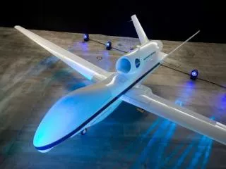
Introduction O • UAV is without pilot, it has some problems when taking the picture from camera because of vibration of UVA when plying due to disturbance such as wind … To overcome this problem; an auto-balancing photogrammetric platform was designed in this project. • A proposed auto-balancing photogrammetric platform includes an Inertial Measurement Unit (IMU) for measuring three angles of Roll, Pitch, and Yaw. • With this proposed platform, we can easily take a photo from camera with small disturbance by auto adjusting three angles of Roll, Pitch, and Yaw to get desired direction
A proposed platform includes a 4-link mechanism for motions around three directions corresponding to three angles of Roll, Pitch, and Roll which are measured by an Inertial Measurement Unit (IMU). • Three servo motors are used as actuator for rotating around three directions. This proposed platform will be mounted at UAV. • Direction of platform can be set and controlled by a microcontroller via PID algorithm. Schematic of a proposed platform was shown in Figure . Proposal auto balancing platform
Step by step solving rotation (attitude) of an IMU O • Step 1 : Initialization (alignment): To determine the initial attitude including roll, pitch, and heading . • Step 2 : Parameter transformation. • Step3 : Update attitude . Figure 1: local level frame Figure 2: Attitude presentation
Step 1: Initialization (alignment): To determine the initial attitude including roll, pitch, and heading of the IMU at start time k Determining roll and pitch (Leveling): Assumption: For error-free accelerometers, the measurements fx and fy represent the tilt in the x and y directions of the vertical accelerometer, i.e. fx = g sin () ; fy = g sin ) where and are the tilts in the x and y directions respectively (usually called roll ( and pitch ()). Therefore = arcsin(fx/g) =arcsin(fy/g)
The heading is commonly determined based on a magnetometer. The Earth’ magnetic field He can be projected into the x, y, z exes in the body frame of the magnetometer. To get the magnetic heading, first, the magnetic field along x axis Hx and y axis Hy are compensated for the un-leveling of the system by the below equation: Where , , and are the output of the magnetometer, and are roll and pitch of the system respectively. Determining heading (Gyro compassing)
The magnetic heading is then determined by the below equation: • The Earth’ magnetic heading is then compensated for the declination angle to get the l-frame heading (geographical heading): Determining heading (Gyro compassing)
Determine DCM matrix from Euler angles (attitude) Step 2: Parameter transformation • For optimal in computation the attitude is usually expressed in quaternion form:
Convert output of the IMU into and • Commonly, the output of a MEMS IMU are angular rate vector (the angular changes of the body frame with respect to the inertial frame expressed in the body frame) and specific force vector . The corresponding incremental angles and incremental velocities can be calculated as: • (2.11)
The body increment with respect to the l-frame is determined as: • Where: • (The rotational speed of the earth) • is latitude of the current point, if only attitude of the IMU is considered, is given an arbitrary value (eg. ) • If only attitude of the IMU is considered, the Step 3: Update attitude
Updated quaternion: Where: • Calculate updated DCM matrix • Calculate updated attitude: