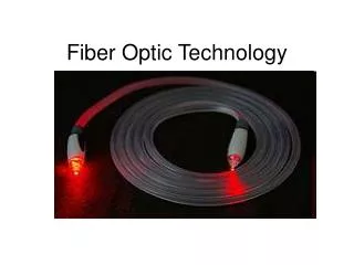
FIBER OPTIC INTERCONNECTION TECHNOLOGY
FIBER OPTIC INTERCONNECTION TECHNOLOGY. 16.05.58 Foundation of DIAMOND SA in Locarno. Processing of diamonds and sapphires for sound systems, industrial jewels, jewels for the watch industry. 1975 Crisis in the watch-making industry … 1978 … diversification began
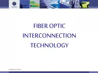

FIBER OPTIC INTERCONNECTION TECHNOLOGY
E N D
Presentation Transcript
FIBER OPTIC INTERCONNECTION TECHNOLOGY
16.05.58Foundation of DIAMOND SA in Locarno. Processing of diamonds and sapphires for sound systems, industrial jewels, jewels for the watch industry. 1975 Crisis in the watch-making industry … 1978 … diversification began 1980 Beginning of production of a series of high precision optical connectors. Applications: telecom, data, video, avionics, submarine etc. In order to keep up with the demand for this new product and to guarantee excellent customer service, the establishment of further subsidiaries was decided. 1985DIAMOND has representatives in 20 countries all over the world. Losone: 200 employees 1987 Further approvals of DIAMOND connectors world-wide. 1993 Development of the new E-2000™ connector 1994 Intensive work in the field of telecommunications, CATV, LAN, sensor applications and measuring technique 1997 Introduction of the new company logo TODAYDIAMOND SA has 10 subsidiaries and 46 representatives organisations in 40 countries with a total of 1000 employees world-wide. A new expantion is under construction. DIAMOND is at the forefront of fiber optics: "DIAMOND, THE FIBER MEETING”. History of DIAMOND SA
Our production • today: • 140.000 connectors manufactured weekly • of which; • 70.000 terminated in our manufacturingfacility in Losone! • tomorrow: beginning in 2001 • 200’000 connectors manufactured weekly • of which; • 120’000 terminated in our manufacturing facility in Losone!
FIBER OPTICS BASICS
Fiber Optic CableComparison with Copper Cable (an example of telecommunication connections) Copper cable Fiber optic cable (coaxial tube) Number of telephone conversation 7'680 33'900 per conductor pair Number of conductor pairs per cable 12 144 Cable diameter (mm) 75 22 Cable weight (kg/km) 8'000 250 Maximum distance between 2 100 repeaters (km)
Properties • Long distance transmission • Increased data transfer thanks to very large bandwidth • No electromagnetic influence • No grounding problems • Small, light and handy cables
Basics 1 x 1 = 3
Light propagation Water tank Expected way of the light Light source Effective way of the light Total reflection at the boundary water-air
Speed of light Vacuum • Speed of light in vacuum: C0 = 299’793 km/sec. • Speed of light in glass: Cglass = 200’000 km/sec. Milan Zurich 1 Millisecond Glas Milan Zurich 1,5 Millisecond
1 Sek. f Frequency t Wavelength Wavelength / Frequency • Wavelength (nm) covered distance of a wave during one period (oscillation) • Frequency (Hz) Number of oscillations (period per second)
Wavelength range of electromagnetic transmission Wavelength 3000km 30km 300m 3m 3cm 0.3mm 3 m m 30nm 0.3nm 2 3 4 5 6 7 8 9 10 11 12 13 14 15 16 17 18 10 10 10 10 10 10 10 10 10 10 10 10 10 10 10 10 10 • Frequency [Hz] NF range HF range Microwaves range Optical range X / gamma range TV & FM radio mobile phone microwave oven analog phone AM radio X-rays
Wavelength range of optical transmission single mode Laser multi mode Laser wavelength nm 1800 1600 1400 1200 1000 800 600 400 200 14 14 15 2x10 3x10 1x10 Frequency Hz Visible range 5x10¹⁴ Radar range Laser range Infrared range Ultraviolet range 1. Optical window 850 nm 2. Optical window 1300 nm 3. Optical window 1550 nm
Perpendicular to division line Light path Division line Division line Light path Perpendicular to division line Reflection Light reflection Total reflection
Light propagation in glass fiber Optical thinner Medium (n2) Light refraction Border ray Optical denser Medium (n1) Total reflection Light source
NA = Sin = n12-n22 Numerical aperture • Coupling the ray of light • The light rays which are outside of the defined angle will be absorbed or propagated within the fiber coating. • Each fiber has its own acceptance respectively reflected beam angle.
Graded index profile - Multimode Fiber Signal at the fiber input Signal at the fiber output Graded Index Fiber • Propagation of several modes • Light conduction by refraction • Fiber cores (50 µm and 62,5 µm)
Step Index profile - Single mode Fiber Signal at the fiber input Signal at the fiber output Single mode fiber • Propagation of a single mode • Fiber core (9µm)
3rd window Dispersion 1st window 2nd window Fiber attenuationTransmission windows
P out [W] a = 10 log = [dB] P in [W] Attenuation The attenuation is given by the logarithmic relationship between the Input and the Output power. -3dB = 1/2 P -10dB = 1/10 P -20dB = 1/100 P -30dB = 1/1000 P
Transmission impulse Receipt impulse Dispersion If a light pulse is coupled within a fiber, then a spreader pulse is to be observed at the fiber end. This impulse spreading increases proportionally with the length.
Fiber construction Single mode coating 250 mm 125 mm 9 mm core cladding 250 mm 125 mm 50/62,5 mm Multi mode
The cable serves to protectthe fiber against: • tensile forces • lateral pressure • humidity • expansion • overbending
Fiber optic cable construction 3000 mm (3 mm) 900 mm (0.9 mm) 250 mm 125 mm 9/50/62,5 mm Core Cladding Primary coating Kevlar thread Secondary coating Jacket
Outdoor cable construction Cladding 125 mm Core 9/50/62,5 mm Primary coating 250 mm Kevlar thread Secondary coating (fiber bundle) Jacket 3000 mm / 3 mm
Loose tube fiber bundle Gel filling Inner loose tube layer, Polyamide Primary coated fiber, 250 m Loose tube fiber Gel filling Inner loose tube layer, Polyamide Primary coated fiber, 250m Tight buffered fiber Secondary coating Primary coating, 250 m Fiber, 125 m Secondary protection techniques Outer loose tube layer, PTBF, Polyester ca. 3 mm Outer loose tube layer, PTBF, Polyester ca. 1.8 mm 0.9 - 1 mm
Loose tube fiber bundle Gel filling Outer loose tube layer, PTBF, Polyester ca. 6-10 mm Inner loose tube layer, Polyamide Primary coated ribbon fiber, 250 m Micro loose tube fiber ca. 0.9 mm Inner loose tube layer, Polyamide Primary coated fiber, 250 m Secondary protection techniques
2 5 6 5 5 5 6 6 Fiber 6 4 7 3 3 5 1 5 8 2 Fiber Block Diagram of an Optical Link 1 Transmitter 2 Receiver 3 Fiber Optics Cable 4 Repeater 5 Connector 6 Splice Connection 7 Splitter 8 Measuring and Service Point • Detachable connecting elements to • connection for active equipment • interconnection points / interface of several networks • measuring, service and switching points in the network
Insertion Loss MeasurementAccording to IEC 1300-3-4 (method 6); CECC 86000 • Measurement for connection cables (patchcords) • Attenuation for both connections and fiber optics fiber
Insertion Loss MeasurementAccording to IEC 1300-3-4 (method 7); CECC 86000 • Measurement for pigtails • Attenuation per fiber optic connections measured value
WDM 1300 Coupler DUT 1550 Detector Display Return Loss Measurement 1) According to IEC1300-3-6; CECC 86000 2) Precision reflectometer • Measurement according to procedure 1) up to max. 55 dB measurement structure for discrete components or equipment configuration for series measuring measured value influenced by the quality of single components • Measurement according to procedure 2) up to max. 90 dB measured value only refers to the measured object
DIAMOND FIBER OPTIC CONNECTOR TECHNOLOGY
Sleeve-ferrule-principle • Sleeve-pin-principle with physical contact of the convex or angle convex polished connector front faces • Consists of a high precision split ceramic sleeve • Does not utilize phosphor bronze or metal to reduce possibility of endface contamination • Ferrule and split sleeve maintain precise tolerances • The antirotation nut prevents rotational movement of the front face:- preventing fiber damage- allowing improved repeatability- enabling precise alignment of fiber and ferrule frontfaces
Fiber coupling 125 mm 9/50/62.5 mm
High precision ferrule • The ferrule incorporates the fiber and guides itconcentrically into the sleeve • The ferrule’s coating is made of corrosion-resistent and non- abrasive material (tungsten carbide or ceramic) • A titanium insert for precise fiber alignment • The ferrule’s diameter of 2,5 mm is defined by international standards • The inner diameter of 128 µm allows for diameter variations of the outer diameter of the 125 µm fiber
Titanium-Insert Zr O2 Fiber Epoxy Crimping technique • The titanium insert is the base for Diamond’s precision termination process including active core alignment techniques • The axial fiber fixation is done with epoxy: The effective gluing zone of only 5 mm length results in reduced pressure from the adhesive on the fiber due to temperature changes • Ensures a constantly low insertion loss for all transmission wavelengths (1310 - 1550 nm)
1st crimping • The Circular V-edge of the crimping piston gently deforms the titanium insert and reduces the hole diameter to the diameter of the fiber • The ferrule hole conforms to the actual fiber diameter including fiber tolerances • The fiber is guided into the center of the hole and ensures uniform distribution of the epoxy • At this point the eccentricity is approx. 1 µm
Active core alignment(2nd crimping) • The second crimp actively aligns the fiber core on the ferrule’s axis • The 120° v-edge of the piston “moves” the fiber in 1/10 µm steps • Light is injected into the fiber in order to illuminate the core. The ferrule is inserted into a high precision Tungsten Carbide sleeve and rotated, in order to detect if there is still any eccentricity between the fiber and ferrule axis • After this operation the eccentricity is reduced to 0.25 µm max • The perfectly aligned fiber core results in consistently low Insertion Loss values for Diamond connectors
For a reference • The core eccentricity of fibers mounted in monoblock ferrules are optimized by rotating the ferrule on the connector body or the antirotation key on the connector body • The accuracy achieved with this method is a position of the core in a area within ± 50° in relation to the antirotation key 50° 50°
Reflection to the front face • Reflections occur on fiber surfaces at the exit as well as entry connector endfaces • Defects on the endface and poor polishing quality, as well as air gaps between the fibers are responsible for reflections • Reflections reduce performance in: • broadband systems • optical fiber repeaters • CATV systems • WDM networks
PC polishing (Convex)Reduction of the reflections • Convex polishing of the fiber surface guarantees fiber contact for reduction of the reflections • Advantages of the titanium-insert • Repeatable polishing • Minimal fiber undercut or protrusion • Less sensitive to fiber undercut or protrusion • Low Reflectance
APC polishing for low reflectance • Angled polished connectors (APC) virtually eliminate reflection by reflecting the light into the fiber cladding to be dissipated • The return loss of an angle polished connector is > 70 dB when unmated • APC polishing of a DIAMOND connector is done with the same effort as a PC polish, no price premium, or performance sacrifice as with other manufacturers
Fiber optics connectors standards • Standardisation is a condition for the compatibility between products of several manufacturers • Comparable optical values such as handling, security and flexibility are decision criteria for the choice of the standards