Download
1 / 16
160 likes | 286 Views
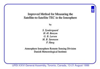
Improved Method for Measuring the Satellite-to-Satellite TEC in the Ionosphere by S. Syndergaard H.-H. Benzon G. B. Larsen M. B. Sørensen P. Høeg Atmosphere Ionosphere Remote Sensing Division Danish Meteorological Institute. Setting the scene: Ionosphere occultation principle.

E N D
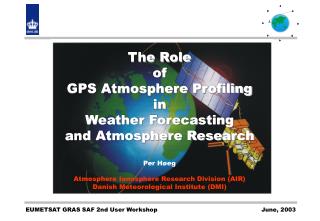
Improved Method for Measuring the Satellite-to-Satellite TEC in the Ionosphere by S. Syndergaard H.-H. Benzon G. B. Larsen M. B. Sørensen P. Høeg Atmosphere Ionosphere Remote Sensing Division Danish Meteorological Institute
Ionosphere tomography combining ground and space measurements Convenient to assume straight lines
GPS observables and traditional TEC measure Disregarding troposphere, clocks & ambiguity bias: • On occultation links the traditional measure is not exactly the straight line TEC • Discrepancy becomes appreciable for large electron density gradients
S-S TEC with first order dispersion correction (“major” term) (“minor” term) • Mainly proportional to the square of vertical TEC gradients • Accuracy depends on validity of spherical symmetry assumption
Simulated TEC residuals, double Chapman layers E-layer: Max. dens.: 2·1011 m-3 Scale height: 5 km F-layer: Max. dens.: 3·1012 m-3 Scale height: 60 km
GPS/MET ionosphere profile, occ. 641, Feb 20 1997 Local time: 12:30 Latitude: 36 N Longitude: 144 E Solar flux: 73
GPS/MET TEC profile, occ. 641, Feb 20 1997 Local time: 12:30 Latitude: 36 N Longitude: 144 E Solar flux: 73
Ørsted ionosphere profile, April 18 1999 Local time: 14:45 Latitude: 33 S Longitude: 13 W Solar flux: 113
Ørsted TEC profile, April 18 1999 Local time: 14:45 Latitude: 33 S Longitude: 13 W Solar flux: 113
Alternative estimate of straight line S-S TEC ) ( traditional combination for comparison • Corrects for first order dispersion effects • Not sensitive to spherical asymmetry • Drawback: clocks and POD needs to be solved (removed)
Summary • Satellite-to-satellite TEC L1 - L2 may give TEC errors • of order 10 TECU • Not a big problem at low solar activity or night time • (error < 1 TECU) • May be a problem at day time, solar maximum • Dispersion correction reduce errors depending on • spherical symmetry assumption • Alternative dual frequency combination can be applied, • but then one needs to solve for clocks and POD • Results can be used in ionosphere tomography to obtain more • accurate straight-line satellite-to-satellite TEC