Download
1 / 17
170 likes | 313 Views
A fast LED driver prototype for HCAL calibration. EUDET annual meeting at Ecole Polytechnique, Palaisau. Proposal for calibration system. New LED driver with reduced crosstalk A tunable calibration light in the range 0 to 100MIP

E N D
A fast LED driver prototype for HCAL calibration EUDET annual meeting at Ecole Polytechnique, Palaisau Ivo Polak, IoP Prague
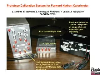
Proposal for calibration system • New LED driver with reduced crosstalk • A tunable calibration light in the range 0 to 100MIP • Simplification of the optical system: one LED -> one side emitting fibre, one row of scintillator tiles • PIN photo diode, do we need them? Ivo Polak, IoP Prague
LED driver strategy for SiPM calibration • At AHCAL prototype (uses SiPM), we used CMB, calibration system with UV-LED 400nm driven by very fast rectangular pulses (1ns rise/fall time). • Steep Rectangular waveform satisfied the needs to vary pulse-width, BUT creates lots of harmonics electromagnetic crosstalk! • We have found fixed pulse-width to about 6ns, we can go to use narrow band ->smooth waveform ≈ less RF interference = Quasi Resonant LED driver (single pulse) Ivo Polak, IoP Prague
Simulation ~ 5ns puls width (slightly depends on the amplitude) 33nH PCB inductance, no ferromagnetic core Prototyping Used my lovely single side copper foil PCB We need more work on components optimization Quasi-Resonant LED driverLC circuit, heavily dumped Ivo Polak, IoP Prague
QR LED driver Simulation oscilloscope oscilloscope Ivo Polak, IoP Prague
Simulation at 1.5V amplitude • XSC1: • Upper trace - sync pulse • Lower trace – voltage at LED hot end • XSC2: Lower trace LED current Ivo Polak, IoP Prague
Simulation at 3V • XSC1: • Upper trace - sync pulse • Lower trace – voltage at LED hot end • XSC2: Lower trace LED current Ivo Polak, IoP Prague
Prototype of QR LED driver Ivo Polak, IoP Prague
LED current waveform (GRN) a=3 Ivo Polak, IoP Prague
LED current waveform (GRN) a=2 Ivo Polak, IoP Prague
LED current waveform (GRN) a=1 Ivo Polak, IoP Prague
Last tests, more power on LED • We see response of PIN photodiode at oscilloscope • Amplitude up to 2mVpeak @ 50 Ω Ivo Polak, IoP Prague
Response to low amplitude • LED current (cyan) (voltage @ 10Ohm) • PIN response (yellow) • LED anode (violet) Ivo Polak, IoP Prague
Response to middle amplitude Ivo Polak, IoP Prague
Response to high amplitude • 200mA current at LED Ivo Polak, IoP Prague
Response to high amplitude • The Light from LED was optically blocked to PIN. Ivo Polak, IoP Prague
Conclusion • QR LED driver is very promising technique to reduce Electro-Magnetic-Interferences • PCB of the two-channel QR LED driver is being designed now • End of October - PCB will be assembled – ready for tests • November – summary report to EUDET • November – measurements of light transfer in side-emitting fibres Ivo Polak, IoP Prague