Download
1 / 16
160 likes | 181 Views
Enhance understanding of seismicity in Northern Mississippi embayment by applying advanced methodologies to generate comprehensive earthquake focal mechanisms catalog. Utilized data from 2000 to 2007, analyzed focal mechanisms using FPFIT and FOCMEC methods, and mapped distribution to study seismotectonic model. Preliminary results reveal key insights into stress tensor determination and fault plane characteristics.

E N D
Purpose • History: Limited number of available focal mechanisms • Herrmann: Surface wave studies of larger events • Lui: Microearthquake focal mechanisms using • waveform modeling and PANDA data • Chiu: P-wave first motion study from PANDA • recorded events • New three component data: 2000-2007 • Better locations – s-wave picks • SH-wave polarity • Generate a more complete catalogue of earthquake focal mechanisms • Seismotectonic model
Study Area • New Madrid Seismic Zone • •Seismicity • Northern Mississippi embayment • Structure • Embayment structures • Focal mechanisms available • Herrmann - 16 • Lui - 54 • Chiu - 9 • Allison Shumway - ?
Data • Pre-1995: single component data and PANDA data • 1995-1999: New Madrid seismic network updates • • 96 three-component stations and 13 broadband seismometers • 2000-2007 data set: 1567 events • md ≥ 4.0 - 4 events • 3.0 ≤ md < 4.0 - 13 events • 2.0 ≤ md < 3.0 - 284 events • 1.0 ≤ md < 2.0 - 1190 events • 0 < md < 1.0 - 76 events
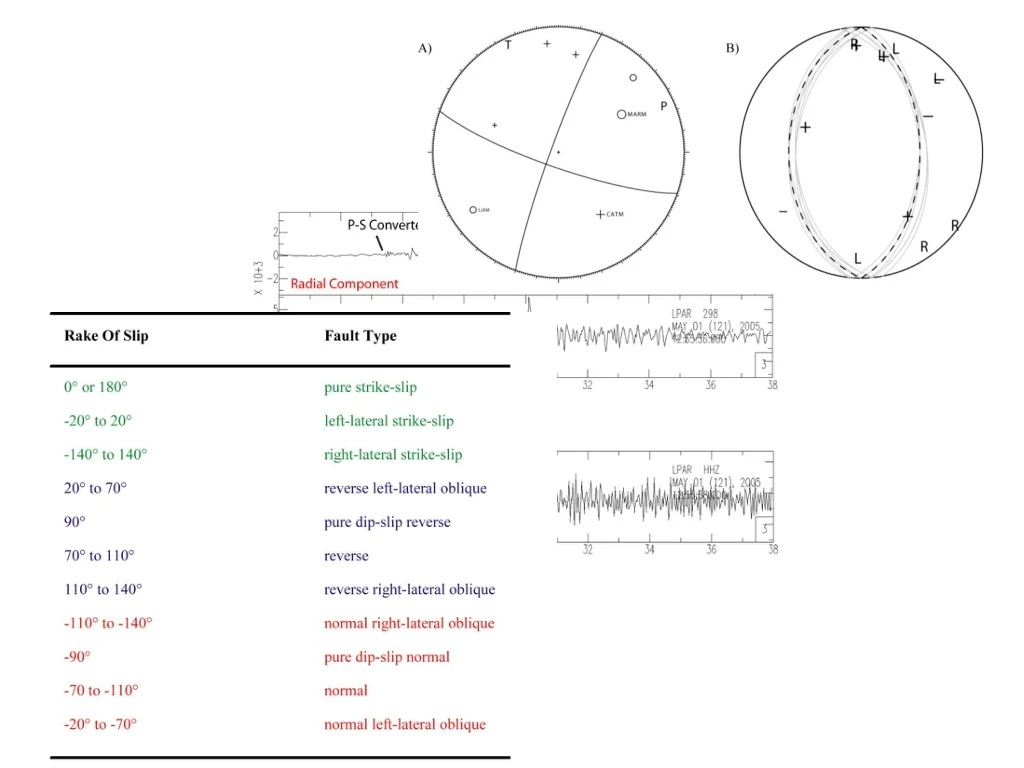
Method - Generation of earthquake focal mechanisms • FPFIT • Use only P-wave Polarity • Parameter Estimate: • Strike = 200° ± 15 • Dip = 85° ± 28 • Rake = - 5° ± 35 • Constrained FM when uncertainty ≤ 20° • FOCMEC • Combine SH- first motion polarity observations • Parameter Estimate • Strike = 180° ± 6 • Dip = 40° ± 5 • Rake = 90° ± 8
Method - Mapping focal mechanisms 1) Distribution of focal mechanisms on segments 2) Categorize type by rake 3) Characterization
Preliminary Results • Central segment: 28% of focal mechanisms identified with this segment show reverse slip on a nodal plane striking ~N21W with ~45º dip to the southwest • Totals Reverse slip: 50% Strike slip: 21% Normal slip: 29% • Southern segment: 19% of the focal mechanisms identified with this segment show right-lateral strike-slip on a nearly vertical nodal plane striking ~N50E • Totals Reverse slip: 35% Strike slip: 49% Normal slip: 16% • Northern segment: 45% of the focal mechanisms identified with this segment show right-lateral strike-slip on a nearly vertical nodal plane striking ~N30E • Totals Reverse slip: 41% Strike slip: 55% Normal slip: 4%
Figure 1-1. Map showing focal mechanisms from past studies. Refer to Table 1 for information on each one. The light gray circles are locations of historic seismicity from 1974 to 2007. Locations of earthquake focal mechanisms from this study are represented by the dark gray circles. The thick gray line is an outline of the Mississippi Embayment.
Determining the stress field from focal mechanism solutions Objective is to find a uniform stress tensor that minimizes the discrepancy between the predicted shear stress direction and the observed slip direction on each fault plane. Start with the regional stress field from the world stress map. For each fault plane in the set of focal mechanism solutions, determine the predicted shear stress direction – the rake. Invert for the stress field that minimizes (observed rake – predicted rake) for all fault planes. Inversion yields an estimate of the best-fitting principal stress directions and the ratio R=(σ2 – σ1)/(σ3 – σ1) R < 0.5 σ1 and σ2 are similar magnitudes R > 0.5 σ3 and σ2 are similar magnitudes
R < 0.5 σ1 and σ2 are similar magnitudes R > 0.5 σ3 and σ2 are similar magnitudes σ1/σ2/σ3 dip strike/dip strike/dip strike Below each histogram Strike-slip Thrust faults