
Enhancing Radiation Detectors with Float Glass Electrodes
Explore the use of float glass as electrodes in radiation detectors, with a focus on RPC aging issues and glass characterization studies. Discover the benefits of Japanese glass and comparative analysis of glass types.

Enhancing Radiation Detectors with Float Glass Electrodes
E N D
Presentation Transcript
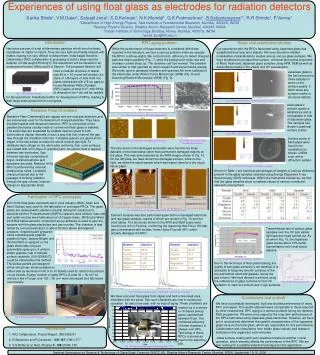
Experiences of using float glass as electrodes for radiation detectors Sarika Bhide1, V.M.Datar2, Satyajit Jena3, S.D.Kalmani1, N.K.Mondal1, G.K.Padmashree1, B.Satyanarayana1*, R.R.Shinde1, P.Verma1 1Department of High Energy Physics, Tata Institute of Fundamental Research, Mumbai, 400005, INDIA 2Nuclear Physics Division, Bhabha Atomic Research Centre, Mumbai, 400085, INDIA 3Indian Institute of Technology Bombay, Powai, Mumbai, 400076, INDIA *email: bsn@tifr.res.in Introduction Neutrinos are part of a set of elementary particles which form the basic constituent of matter in nature. They are very light and hardly interact with matter, making it is very difficult to detect them. India-based Neutrino Observatory (INO) collaboration is proposing to build a large neutrino detector of total weight 50 kton[1]. The experiment will be situated in an underground tunnel, 90km south of Mysore. The proposed detector will RPC aging problem While the performance of these detectors is consistent with those reported in the literature, we face a serious problem when we operate the RPCs continuously[3]. We notice that its efficiency to detect charged particles drops suddenly (Fig. 7), while the background noise rate and chamber current shoot up. The chamber can’t be revived. The problem was similar to that reported by other research and experimental groups. We broke open a damaged chamber and scanned the inner surfaces of the electrodes under Atomic Force Microscope (AFM) (Fig. 8) and Scanning Electron Microscope (SEM) (Fig. 9). Glass characterisation studies Our experience with the RPCs fabricated using Japanese glass has established their long term stability. We have therefore initiated comparative characterisation studies among various glass samples. We have studied and compared the surface, chemical and optical properties of Modi, Asahi and Japanese glass samples using AFM, SEM as well as transmittance tests in the visible and UV wavelengths. have a modular structure of lateral size 48 m × 16 m and will consist of a stack of 140 layers of 6cm thick iron plates interleaved with 2.5 cm gaps to house Resistive Plate Chamber (RPC) layers. A total of 27, 000 RPCs of dimension 2m × 2m will be needed Japanese glass is the best among the three samples in terms of the surface quality. It didn’t show any surface cracks or structural defects. Fig. 1 INO detector concept for his experiment. A dedicated effort for development of RPCs, leading to their large scale production is in progress. Fig.12 AFM and SEM scans of Japanese glass samples Asahi glass’s surface quality is satisfactory and is comparable to that of Japanese glass. The samples has shown occasional surface cracks. Resistive Plate Chambers Resistive Plate Chambers[2] are rugged and low-cost gas detectors and are extensively used for the detection of charged particles. They have excellent spatial and temporal resolution. RPC is composed of two parallel electrodes usually made of commercial float glass or bakelite. The electrodes are separated by suitable spacers glued to both electrodes at regular intervals in such a way that they channel the gas flow through the chamber uniformly. T-shaped spacers are glued at the edges of the electrodes to make the whole module gas tight. To distribute high voltage on the electrodes uniformly, their outer surfaces are coated with a thin layer of graphite paint. An electric field is applied between two electrodes. Gas Fig. 7 Efficiency history of a RPC getting damaged Fig.13 AFM and SEM scans of Asahi glass samples Surface scans of Modi glass were found to be unsatisfactory. Shown a SEM scan with a diffraction pattern. Fig.8 AFM scans of damaged electrodes and raw glass Fig. 9 SEM scans of damaged electrode and raw glass The structures on the damaged electrodes were found to be loose deposits on the electrodes rather than permanent damaged regions on the glass. This was demonstrated by the AFM images shown in Fig. 10. On the left plate, we have shown the damaged surface, while on the right, we show the same sample which was wiped clean by a dry rough tissue paper. mixtures typically comprising of Argon, tetrafluoroethane and isobutene are used. Readout of the RPC is performed by external metal pickup strips. Localised charge produced due to the passage of ionising radiation through the gas volume, induces charge on appropriate strips. Pickup strips Fig.14 AFM and SEM scans of Modi glass samples T-shaped spacers Shown in Table 1 are fractional percentages of weights of various elements present in the glass samples obtained using Energy Dispersive X-ray Spectroscopy (EDS) technique. Within the instrument tolerances, we find that the glass samples show consistent values of various constituent elements among them. Electrode plates Fig. 2 Schematic of a typical RPC Fabrication of RPC prototypes 2mm thick float glass manufactured in local industry (Modi, Asahi and Saint Gobian) was used for the fabrication of prototype RPCs.The glass plates are cleaned with Labolene (neutral detergent) solution and absolute alcohol. Polycarbonate (NORYL) spacers were utilised. Gas inlet and outlet nozzles were fabricated out of Copper tubes. 3M Scotch-Weld 2216 B/A translucent two component epoxy adhesive is used to glue the spacers with the glass electrodes and gas nozzles. The chamber is leak tested by over pressurising it to about 20mbar above atmospheric pressure. Graphite paint prepared Fig. 10 AFM scans of damaged electrode and after wiping it clean Element analysis was also performed again both on damaged electrode and raw glass samples, results of which are shown in Fig. 10 and the inset tables. The structures shown in the AFM and SEM scans were found to be rich in Fluorine, confirming the reasoning that Freon (R134a) gas contaminated with moister, forms Hydro Fluoride (HF), which actually damages the RPC. Table 1 Summary of EDS results of various glass samples Transmittance test of various glass samples over the UV and visible light spectrum was carried out. As shown in Fig. 15, the Japanese glass shows about 10% better transmittance over local brand glasses. using colloidal grade graphite powder(3.4gm), lacquer(25gm) and thinner(40ml) is sprayed on the glass electrodes using an automobile spray gun. A uniform, stable graphite coat of desired surface resistivity (100-200K/) could be obtained by this method. The pickup panels are designed either using foam sheets padded on Fig. 15 Transmittance test results glass samples Due to the technique of float glass making, the quality of two glass surfaces is not identical. It is advisable to keep two smooth surfaces of the top and bottom electrode glasses, facing the gas volume. We have devised a scheme using the reflectance of glass surfaces for the UV Fig. 3 Surface resistivity of graphite coat either side by aluminium foils or G-10 sheets used for electronics printed circuit boards. A large number of glass RPCs of area 30 × 30 cm2 as well as a few of larger size 120 × 90 cm2 were developed and fabricated successfully. Fig. 16 Side determination test radiation to mark the smooth and rough surfaces. Fig. 10 Element analysis results of damaged electrode and raw glass We have procured float glass from Japan and built a few small area chambers with the same. Two such chambers are now in continuous operation for about one year, with no sign of aging. These chambers are Conclusions and outlook We have successfully developed, built and studied performance of many RPC prototypes. The results obtained were comparable to those reported by other researchers. RPC aging is a serious problem facing our detector R&D programme. We were encouraged by the long term performance of the RPCs fabricated using Japanese glass electrodes. However, we have yet to conclusively determine the specific characteristics of the Japanese glass vis-à-vis the local glass, which are responsible for this performance. Collaboration and consultancy from Indian glass industry and research institutes in this regard are most welcome. Glass surface coating with semi-resistive material is another crucial operation, which severely affects the performance of the RPC. We are also looking for a suitable industrial technique for this application. readout by a common G-10 based pickup panel, sandwiched between them. The combined efficiency of these chambers is always over 94%. Test setup of these RPCs is shown as inset in the adjoining plot. Fig. 4 Small area RPC prototype Fig. 5 Large area RPC prototype • References • INO Collaboration, Project Report, INO/2006/01 • R.Santonico and R.Cardarelli, NIM 187 (1981) 377 • S.S.Bhide et al, Nucl. Physics B, 158 (2006) 195 Fig. 11 Long term stability plot of Japanese glass RPCs National Symposium on Science & Technology of Glass/Glass-Ceramics (NSGC-06), Bhabha Atomic Research Centre, Mumbai, INDIA, September 15-16, 2006


