Download
1 / 52
520 likes | 694 Views
Guitar Amplifier with Analog/Digital Effects (Senior Design Project Fall/2013). Group 5 Members: Alex Chen Audrey Hernandez Brittany Delose Robert John. Motivation. Explore music and technology Have analog and digital effects User control

E N D
Guitar Amplifier with Analog/Digital Effects (Senior Design Project Fall/2013) Group 5 Members: Alex Chen Audrey Hernandez Brittany Delose Robert John
Motivation Explore music and technology Have analog and digital effects User control Produce a quality output for the musician and listeners
Objectives Amplifier housing is easily moveable Controlled output power Quality output that is low noise over a wide volume range User controlled effect systems Wireless user interface
Analog Effects Specifications +9V supply .25 W 1206 Resistors >= 16V electrolytic and aluminum capacitors Linear and Audio rotary Potentiometers
The Fuzz Box MMBT222A NPN bipolar transistor Low power amplification Low current High switching speeds SOT-23 package Potentiometers 1 K linear (fuzz) 500 K audio (volume)
Big Muff MMBT5088 NPN general purpose amplifier High gain Low noise SOT-23 package Potentiometers 2 100k Linear (Tone and Sustain) 1 100k Audio (Volume)
Distortion with Stutter LM386M-1 Low voltage External gain of 200 Voltage range 4-12 V Low quiescent current a mA 8-SOIC NE555DR Precision timing oscillator programmable duty cycle Voltage range 5-15V 8-SOIC
Orange Squeezer MMBJF310 • N-Channel JFET Amplifier • Voltage rated 25 V • Quiescent current 60 mA • SOT-23 TL072ACD • JFET input op-amp • low input bias • fast slew rate • 8-SOIC
Octave Up N4148W Fast switching speed Fast reverse recovery SOD-123 package NE5532ADR General purpose (pre) amplifier Low level Low noise 8-SOIC
Tremolo MMBT3906 NPN Transistor Ideal for medium power amplification SOT-23 Potentiometers 1 100 K Linear (Duty Cycle) 1 100 K Audio (Volume)
Digital Effects TI’s TMS320C5515 eZdsp was the prototype board selected Digital effects algorithms designed on the prototype board PCB layout for the digital effects based off the prototype board
TMS320C5515 eZdsp TMS320C5515 16 bit fixed point DSP TLV320AIC3204 for ADC and DAC conversions 48ksps Eighth inch Stereo input and output jacks USB 2.0 Interfaces with TI’s Code Composer Studio Within budget
Reverberation • Reverberation works by adding the current input to a delayed output • There are two main parameters to the effect, the depth and size of the reverberation array • Depth determines amount delay of the signal that is added to the input • The size of reverberation array determines the amount of the previous signal is saved
Fuzz • The fuzz effect compares the guitar input to three conditions • Ifthe input between a parameter +X and -X passed through • If the input is less than -X it is set to a fixed value - Y • If the input is greater than X is it set to +Y
Echo • The echo effect works by adding the current input to a delayed input • There are two main parameters to the effect, the depth and size of the echo array • Depth determines amount delay of the signal that is added to the input • The size of the echo array determines the amount of the previous signal is saved
Tin Can • This is a highly treble sounding effect • The treble and the bass components of signal are separated • Higher frequencies passed • Low frequencies are filtered by downsampling
Phase • This effect works by varying the size of delay between values in a buffer array • The size of the buffer and the amount of maximum delay are the two main parameters • The guitar input and the delayed value are both down sampled then upsampled when returned to main
Robot • A sine wave is generated then it is multiplied with the guitar input • The frequency of the sine wave can be increased or decreased to modify the effect
Fuzzy Tube The modulation is between the guitar input and a modified sine wave The sine wave is modified by setting it’s amplitude to a respective fixed amplitude When the sine wave is positive and negative it’s fixed to its respective values The sine wave becomes clipped
User Interface • Netbeans IDE -Free, open-source, growing community of users/developers • Select between 7 effects, modify certain parameters
User Interface Reverb effect - Update button notifies DSP - To change to another effect, current window must be closed - Only the main window will close application
Bluetooth Evaluation Boards PAN1323ETU - Plugs directly into the MSP430F5430 Experimenter Board - BT stack provided free - Matching P1/P2 pinouts - Contacted SSO; BT stack not developed for the TMS320C5515ezDSP
Bluetooth Evaluation Boards ● RN-42-EK - Embedded BT stack (CSR BlueCore-04) - FT232RQ - 4 configuration switches - PCB trace antenna - 3Mbps Data Rate - Baud Rate - Error correction, auto-discovery/pairing, auto-connect master
Plan for GUI/DSP Usb4java -Serial port emulation DSP Bootloader -Flash new code
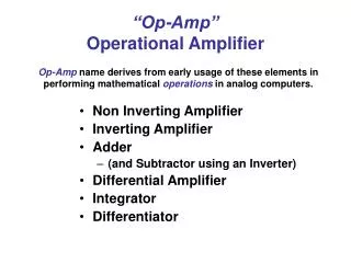
Advantages of Op Amps over Discrete • Components matching • High CMRR • High gain • Lower power consumption • Simplicity • Low cost • TI’s high precision low noise OPA134 was selected. Pre Amplifier Functions Prepares signal for further amplification Provides necessary voltage gain Controls the volume and equalization Cleans up a signal by eliminating high frequency noise
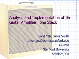
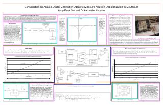
Pre Amplifier Block Diagram Band pass filter obtains range from 5 Hz to 1 MHz First stage and second stage Op Amps each provides about voltage gain of 10 “Tone stack” equalization circuit for low, mid, and high tone control. Volume control is done by adjusting the input of second stage Op Amp
Pre Amplifier Schematic
Pre Amplifier Frequency Response and Distortion
Pre Amplifier PCB Layout and 3D View
Power Amplifier Functions Provides high current gain Provides enough output power to drive a speaker Design Concept A 50W output power amplifier for an 8 Ohms speaker requires: Vrms = 20V, Vpeak = 28V, Irms = 2.5A, Ipeak = 3.5A
Power Amplifier Block Diagram Differential circuit w/ constant current source for input stage Common emitter amplifier for middle stage Class AB in Darlington pair for output stage Circuit protection for short load No IC’s used for more control and high current requirements
Power Amplifier Schematic
Power Amplifier Frequency Response and Distortion
Power Amplifier PCB Layout and 3D View
Power Supply Function Converts 115VAC to DC’s needed for the project Filters out as much AC ripples as possible Outputs 30 VDC for power amplifier module 15 VDC for pre amplifier module 9 VDC for analog effects module 5 VDC for digital effects module
Power Supply Block Diagram Center tapped with secondary output 24VAC and power rating of 100VA transformer 100V/4A full wave bridge rectifier Simple RC filter LM78XX and LM79XX voltage regulator IC’s
Power Supply Schematic
Power Supply PCB layout and 3D view
Budget and Financing Estimate Total: $850
Successes and Difficulties Successes Satisfied SPICE simulation results on all modules Successful digital effects coding on DSP evaluation board Board design and layout for analog effects More than half PCB’s on order Possible Difficulties Noise resistance Implementation of boards in cabinet DSP/GUI interfacing