Understanding LC-3 Instruction Set Architecture: Key Concepts and Operations
190 likes | 294 Views
Learn about the LC-3 ISA, memory organization, addressing modes, control and data instructions. Includes details on registers, data types, and branch instructions. Ideal for those interested in programming at the machine language level.

Understanding LC-3 Instruction Set Architecture: Key Concepts and Operations
E N D
Presentation Transcript
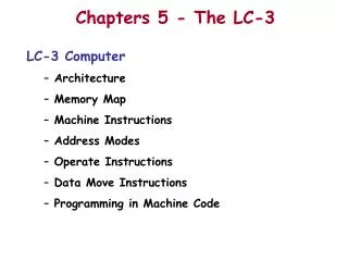
Instruction Set Architecture • ISA = All of the programmer-visible components and operations of the computer • memory organization • address space -- how may locations can be addressed? • addressibility -- how many bits per location? • register set • how many? what size? how are they used? • instruction set • opcodes • data types • addressing modes • ISA provides all information needed for someone that wants towrite a program in machine language(or translate from a high-level language to machine language).
LC-3 Overview: Memory and Registers • Memory • address space: 216 locations (16-bit addresses) • addressability: 16 bits • Registers • temporary storage, accessed in a single machine cycle • accessing memory generally takes longer than a single cycle • eight general-purpose registers: R0 - R7 • each 16 bits wide • how many bits to uniquely identify a register? • other registers • not directly addressible, but used by (and affected by) instructions • PC (program counter), condition codes
LC-3 Overview: Instruction Set • Opcodes • 15 opcodes • Operate instructions: ADD, AND, NOT • Data movement instructions: LD, LDI, LDR, LEA, ST, STR, STI • Control instructions: BR, JSR/JSRR, JMP, RTI, TRAP • some opcodes set/clear condition codes, based on result: • N = negative, Z = zero, P = positive (> 0) • Data Types • 16-bit 2’s complement integer • Addressing Modes • How is the location of an operand specified? • non-memory addresses: immediate, register • memory addresses: PC-relative, indirect, base+offset
Operate Instructions • Only three operations: ADD, AND, NOT • Source and destination operands are registers • These instructions do not reference memory. • ADD and AND can use “immediate” mode,where one operand is hard-wired into the instruction. • Will show dataflow diagram with each instruction. • illustrates when and where data moves to accomplish the desired operation
NOT (Register) Note: Src and Dstcould be the same register.
this zero means “register mode” ADD/AND (Register)
this one means “immediate mode” ADD/AND (Immediate) Note: Immediate field issign-extended.
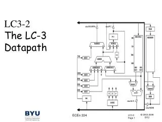
LC-3 Data PathRevisited Filled arrow = info to be processed. Unfilled arrow = control signal.
Using Operate Instructions • With only ADD, AND, NOT… • How do we subtract? • How do we OR? • How do we copy from one register to another? • How do we initialize a register to zero?
Control Instructions • Used to alter the sequence of instructions(by changing the Program Counter) • Conditional Branch • branch is taken if a specified condition is true • signed offset is added to PC to yield new PC • else, the branch is not taken • PC is not changed, points to the next sequential instruction • Unconditional Branch (or Jump) • always changes the PC • TRAP • changes PC to the address of an OS “service routine” • routine will return control to the next instruction (after TRAP)
Condition Codes • LC-3 has three condition code registers:N -- negativeZ -- zeroP -- positive (greater than zero) • Set by any instruction that writes a value to a register(ADD, AND, NOT, LD, LDR, LDI, LEA) • Exactly one will be set at all times • Based on the last instruction that altered a register
Branch Instruction • Branch specifies one or more condition codes. • If the set bit is specified, the branch is taken. • PC-relative addressing:target address is made by adding signed offset (IR[8:0])to current PC. • Note: PC has already been incremented by FETCH stage. • Note: Target must be within 256 words of BR instruction. • If the branch is not taken,the next sequential instruction is executed.
BR (PC-Relative) What happens if bits [11:9] are all zero? All one?
LC-3 Data PathRevisited Filled arrow = info to be processed. Unfilled arrow = control signal.
How are Branches Used? • Alter the flow of the program,based on some programmer-specified condition,evaluated at execution time. • Two basic constructs: • Iterative(Loops) • execute instruction sequence multiple times • Conditional (If, If-Else) • choose whether or not to execute instruction sequence
Iterative While Loop Do-While Loop
Code for Iteration PC offset to address C Exact bits depend on condition being tested Unconditional branchto retest condition PC offset toaddress A Assumes all addresses are close enough that PC-relative branch can be used.