Download
1 / 6
60 likes | 208 Views
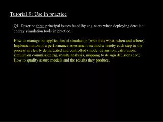
Tutorial 9: Use in practice. Q1. Describe three principal issues faced by engineers when deploying detailed energy simulation tools in practice. How to manage the application of simulation (who does what, when and where).

E N D
Tutorial 9: Use in practice Q1. Describe three principal issues faced by engineers when deploying detailed energy simulation tools in practice. How to manage the application of simulation (who does what, when and where). Implementation of a performance assessment method whereby each step in the process is clearly demarcated and controlled (model definition, calibration, simulation commissioning, results analysis, mapping to design decisions etc.). How to quality assure models and the results they produce.
Q2. In relation to integrated building performance simulation, identify three progressively detailed input levels and the performance assessments then made possible. Select a relevant example from each section ‘Early’, ‘Intermediate’ and ‘Detailed’: Cumulative model description Typical performance assessment enabled Early: pre-existing database implied performance indicators (e.g. material hygrothermal and embodied energy data etc) + geometry visualisation, photomontage, shading, insolation etc + constructional attribution embodied energy, material quantities, time constants etc + operational attribution casual gains, electricity demands etc + boundary conditions photo-realistic imaging, illuminance distribution, no-systems thermal and visual comfort levels etc Intermediate: + special material selectricity generation (photovoltaics), daylight levels (switchable glazings) etc + control system daylight utilisation, energy performance, system response etc + flow network natural/mechanical ventilation, heat recovery etc + HVAC network psychrometric analysis, component sizing etc Detailed: + CFD domain indoor air quality + electrical network renewable energy integration, load control etc + enhanced resolution thermal bridging + moisture network local condensation, mould growth and health.
Q3. In relation to energy systems simulation, select five principal program input parameters, state the nature of a related uncertainty and suggest what action might be taken to reduce this uncertainty. Any 5 from: Climate: A stochastic system that is inherently uncertain. Micro-climate phenomena - wind hollows, urban canyons, vegetation related cooling etc - can have significant impact. Models may be subjected to a range of boundary conditions in order to test the robustness of a given design hypothesis. Lighting: Clouds and pollution, will impact on the sky luminance distribution. Indoor surface finishes, photocell response characteristics and lamp emissions have an associated uncertainty deriving from the manufacturing process and calibration/maintenance considerations. It is possible to assume optimistic and pessimistic scenarios to ensure an adequate lighting provision. Glazing: The thermo-optical properties of glazing may exhibit a significant variation both within a given sample (e.g. from centre to edge) and between samples (e.g. uncertainty in convective heat exchange, particularly with solar shading devices). Context factors - such as frame conduction, urban air pollution, window maintenance, shading device robustness etc - can have a significant effect on performance related properties. Where this is likely, a higher modelling resolution could be adopted. Formand fabric: The translation from design intent to on-site realisation gives rise to many uncertainties in relation to final dimensions, construction composition and tightness. Each of these factors can impact significantly on the final performance of the design. Contemporary concepts, such as breathable facades, PV-integrated facades, transparent insulation, switchable glazings etc., will increase the level of uncertainty inherent in the problem definition process and associated with the selection of the thermo-physical properties of materials.
Q3. Continued Ventilation: The quantification of a building's leakage distribution is an inherently uncertain task and there exists scant guidance on the likely ranges to be found in practice. Likewise, the determination of surface pressure distribution is dependent on the ameliorative effect of local wind shelter phenomena that are the subject of considerable uncertainties. An otherwise sophisticated program may well provide results that are inaccurate and inapplicable. A sensitivity analysis, giving the variation of the results when input data are changed, is usually required. Occupant interactions: The physiological and psychological processes that give rise to particular occupant responses to their environment are not well understood and few models exists for use in predicting how people interact with ventilation, lighting and heating/cooling systems. The levels of heat and moisture production can vary significantly, both between individuals and as a function of the context. Electrical systems: All electrical systems are characterised by fundamental parameters (impedance, capacitance, inductance etc) that are affected by variations in temperature, moisture and demand. As a stochastic process, demand, in particular, gives rise to a significant uncertainty. Many electrical systems - such as PV components, power electronics and rotary generators - are characterized by parameters that relate to standard test conditions (STC). As conditions depart from STC so the applicability of the parameter values, and hence the uncertainty, will grow.
Q4. Describe the steps involved in undertaking a performance assessment using an integrated energy simulation program. For each step give an example of the required action and the related knowledge. Establish a computer representation (e.g. a multi-component plant model with explicit representation of fluid flow and control system) corresponding to a base case design (e.g. regulation compliant or with conservative component sizes). Calibrate this model (e.g. compare predictions to some reference case) using reliable techniques (e.g. inter-model comparison). Locate representative boundary conditions (e.g. of temperature, wind and solar irradiance) of appropriate severity (e.g. typical or extreme). Undertake integrated simulations (e.g. covering energy, mass and momentum balance) using suitable programs. Express multi-variate performance (e.g. peak load, energy demand, environmental emissions, component temperatures etc.) in terms of suitable criteria (e.g. PPD for thermal comfort, JPPD for visual comfort, reverberation time for acoustics, NPI for energy). Identify problem areas (e.g. overheating) as a function of criteria acceptability (e.g. PPD less than 10%). Analyse simulation results (e.g. examine flow-path magnitudes) to identify cause of problems (e.g. excessive solar gain). Postulate remedies (e.g. change control system) by associating problem causes with appropriate design options. For each postulate, establish a reference model (e.g. base case model with a change applied to a justifiable level of resolution. Iterate from step 4 until the overall performance is satisfactory (e.g. thermal comfort is attained for acceptable energy consumption).
Q5. Identify five performance entities that might be displayed in an ‘Integrated Performance View’ and describe how together they might be used to refine the overall performance of a design. • seasonal fuel and power consumption; • environmental emissions; • thermal comfort; • visual comfort; and • installed plant capacity. • Taken together, these performance entities allow a balance to be struck between comfort requirements, energy use and environmental impact.