Download
1 / 27
290 likes | 508 Views
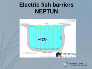
Electric fish barriers NEPTUN . Key Design Features. “Informational” electric field - electric energy absorbed to scare not to stun the fish. Random alterations – prevent adaptation to constant electric field. Ease of installation Size flexibility Resilience and robustness

E N D
Key Design Features • “Informational” electric field - electric energy absorbed to scare not to stun the fish. • Random alterations – prevent adaptation to constant electric field. • Ease of installation • Size flexibility • Resilience and robustness • Resistance to low temperature (icing). • Low energy consumption (solar panels for small barriers) • Low maintenance costs.
Features That Set Neptun Apart • Non-linear distribution of the electric field in water, contrast to classical barriers where the electric field intensity in the area between the electrodes is constant regardless of fish location (next slide). • Intensity of the electric field • positive electrodes - close to zero • negative electrodes maximum. • Adjustable DC pulse parameters: • amplitude, • pulse duration, • intervals between the pulses • number of pulses in a packet.
Gradient of the electric field : classic electric barrier vs NEPTUN technology U = E x L where: U – voltage accumulating on the fish’s body E – current intensity L – fish’s length 1 – average gradient E at all sections of the electric barrier (U1) 2 - average gradient E at all sections of the electric-electronic barrier (U2) 3 – direction of fish movement B=D classic electric barrier C>A NEPTUN technology => The closer the fish the stronger the field !!
Gradient of the electric field : classic electric barrier vs NEPTUN technology U = E x L where: U – voltage accumulating on the fish’s body E – current intensity L – fish’s length 1 – average gradient E at all sections of the electric barrier (U1) 2 - average gradient E at all sections of the electric-electronic barrier (U2) 3 – direction of fish movement A>B>C classic electric barrier A<B<C NEPTUN technology => Size matters but distance matters more!! Selectivity possible.
Example of the single electrode Electrodes are attached to a line along the bottom (next slide) and have floats on top to hold them in vertical position Electrodes are flexible and allow passage of debris, etc. Ideally, a concretefloorisused to anchortheelectrodes, but not necessarily
Rope to which the electrodes are attached is mounted to the bottom
The electronic equipment of the control and power supply systems – open switchbox, the weir in Krzywaniec, Bóbr River.
Technical parameters • length : 93 m • length of a single electrode: 2.2 m for electrodes with positive and negative polarisation • electrodes: acid resistant steel A4 • electrodes mounting : anchored to a concrete block at the bottom of the reservoir • power supply for the control and power supply system: 3-phase, through a separate transformer, • (1-phase possible) • average power intake : 0.43-0.45 KWh
Installation on the weir in Krzywaniec, Bóbr River. Electrodes Positive polarization (+) to Hydropower Plant Electrodes Negative polarization (-) Electronics
Acoustical monitoring of fish at an electric barrier –NEPTUN EY 500 split beam echo-sounder with the transducer directed horizontally. Krzywaniec reservoir / Dychow complex hydraulic engineering, on the river Bobr Stationary measurements powered and not powered (next two slides)
Barrier off… presence of fish between electrodes detected by hi-res sonar Fish are everywhere; N=283, scanned for 4 minutes
Barrier on for 20 minpresence of fish between electrodes detected by hi-res sonar Few fish attempting to cross the field; N=10; scanned for 4 minutes
Minimum Technical parameters required for design • Design criteria: • Site map showing intake, outlet of turbines, fish-passes; • Depth and electric conductivity of water • Substrate • Mean cross sectional velocity (no greater than 0.5 m/s) • Available power supply (1- or 3-phase)
Neptun Benefits • Increasing field intensity • Electric field depth-independent • Electric field can be depth-dependent • Low power consumption (solar for small barriers) • Low operation and maintenance costs • Safer • Electricity does not disperse into the ground • No depth limitation • …
Neptun Benefits • No debris interference • Does not affect navigation • Safety and operation logging • Remote control • Can be installed anywhere (new or retrofit) • Many applications • Low purchase and installation costs • More humane