
whofle:
whofle:. W. Hofle CERN AB/RF. Feedback systems. Introduction to feedback systems in Accelerators. An accelerator is a complex system that requires many parameters and sub-systems to be dynamically controlled and stabilized.

whofle:
E N D
Presentation Transcript
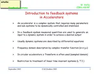
whofle: W. HofleCERN AB/RF Feedback systems Introduction to feedback systemsin Accelerators • An accelerator is a complex system that requires many parameters and sub-systems to be dynamically controlled and stabilized. • In a feedback system measured quantities are used to generate an input to a dynamic system in order to achieve a desired output • Usually dynamic systems are described by differential equations • Frequency domain description by complex transfer function (s=s+jw) • In circular accelerators z-Transform is often used (sampled domain) • Restriction to treatment of linear time invariant systems (L T I ) CAS Zeuthen 2003
whofle: W. HofleCERN AB/RF Feedback systems Reminder Transforms + o o Fourier Transform X(f) = x(t) e -jwt dt - o o + o o Laplace Transform Y(s) = y(t) e -st dt 0 + o o z-Transform F(z) = f(nt) z-n n=0 CAS Zeuthen 2003
whofle: W. HofleCERN AB/RF Feedback systems System response in frequency domain X(s) Y(s) G(s) d2y(t) Example harmonic oscillator: + w02 y(t) = x(t) dt2 x(t) describes an external perturbation y(t) describes the time evolution of the system output (response) 1 Transfer function: G(s) = with s=jw (positive/negative w!) s2 + w02 1 G(w) = w02 - w2 CAS Zeuthen 2003
whofle: W. HofleCERN AB/RF Feedback systems Feedback path X(s) Y(s) G(s) Feedback path: H(s) • H(s) includes transfer functions of • sensors • signal processing • actuators • and always some delay! + - H(s) Output with feedback loop closed: Y(s) = G(s) X(s) - G(s) H(s) Y(s) G(s) Closed loop transfer function: F(s) = 1 + G(s) H(s) Open loop transfer function: G(s) H(s) CAS Zeuthen 2003
whofle: W. HofleCERN AB/RF Feedback systems Stability jw x For stability poles of closed loop transfer function F(s) must lie in negative half plane when z transform is used poles must lie inside unit circle s x G(s) Closed loop transfer function: F(s) = 1 + G(s) H(s) CAS Zeuthen 2003
whofle: W. HofleCERN AB/RF Feedback systems Example: RF cavity feedback Z(s) cavity impedance Ib(s) V(s) Z(s) • H(s) includes transfer functions of • coupling antenna • signal processing • RF power amplifiers • cavity coupling + + Ig(s) H(s) Ib Ig V C R Z(s) L Closed loop transfer function: F(s) = 1 - Z(s) H(s) cavity Purpose: cancel beam induced voltage, reduce impedance seen by beam Feedback gain limited by delay (stability), note feedback closed around cavity RF cavity feedback absolutely essential for high beam currents, super-conducting cavities CAS Zeuthen 2003
whofle: W. HofleCERN AB/RF Feedback systems Beam feedback system Feedback path closed around beam G(s) includes characteristics of beam as dynamic system examples are “coupled bunch feedbacks” (transverse and longitudinal plane) with use of RF amplifiers and electromagnetic kickers, cavities, magnetic or “electro-static” deflectors, usually “fast” (turn-by-turn) very often wide-band these systems are wide band other examples: tune feedback, orbit feedback actuators are magnets, usually “slow” For theory of coupled bunch instabilities see talk by K. Schindl Coupled bunch feedbacks widely used in high intensity proton and lepton circular accelerators Purpose of coupled bunch feedbacks: Provide stability and damp injection oscillation before filamentation occurs CAS Zeuthen 2003
whofle: W. HofleCERN AB/RF Feedback systems Coupled bunch feedback in circular accelerators T0 : beam revolution time f0 : revolution frequency assume t signal =tbeam + MT 0 M=0 -> very often not possible (ultra-relativistic beams!) M=1: very common -> “One -Turn-Delay” feedback one-Turn delay corresponds to multiplication kicker t signal t beam Signal processing in f-domain, (Fourier transforms) with: e-jwT0 Pick-up in s-domain, (Laplace transforms): e-sT0 in z-domain, (z transforms): z-1 Longitudinal plane: ws << w0 -> many turns per oscillation period Transverse plane: wb = (n+q)w0 - >many oscillation periods per turn CAS Zeuthen 2003
whofle: W. HofleCERN AB/RF Feedback systems Transverse feedback Consider slice of beam or bunch excersing a coherent betatron oscillation - pick-up measures position y - kicker corrects angle y’ D phase advance between pick-up 1 and pick-up 2 / kicker signal of slice of beam on turn n at pick-up 1 (t=nT0) yPU (t) = (JbPU)1/2 cos(2pQt) at kicker yK(t’) = (JbK)1/2 cos(2pQt’+D) t’ = t + t beam kick by feedback system Dy’K (t’) = g (JbPU)1/2 cos(2pQt’) Kicker bK t signal Pick-up 2 Signal processing gain g t beam D Pick-up 1 bPU angle at kicker: y’K = (t’) = - (J/bPU)1/2 (a cos(2pQt’+D) + sin(2pQt’+D) CAS Zeuthen 2003
whofle: W. HofleCERN AB/RF Feedback systems Transverse feedback x’ x’ Bunch on turn n=1 Dy’ x x Bunch on turn n=1 Bunch on turn n=0 Dy’ Bunch on turn n=0 area pJ area pJ at pick-up 1 at kicker peak kick Dy’ = g (JbPU)1/2 effective average kick is only half of the peak kick (averaging betatron phases) min damping time t = (T0/2) g (bPU bK)1/2 for D = ? CAS Zeuthen 2003
whofle: W. HofleCERN AB/RF Feedback systems further complications pick-up at optimum phase may not be available - use two pick-ups in quadrature to generate a signal at the desired phase - use a single pick-up and combine signals from M previous turns (-> Hilbert filter, FIR), disadvantage: tune sensitive large closed orbit variations in pick-up - use notch filter: F notch = 1-z-1 -> gain at revolution frequency harmonics is zero: attention signal shifted in betatron phase (half a turn!) fast damping and tunes close to integer or half integer -> unstable - avoid being close to half integer and integer resonance - use two kickers p/2 apart for smooth damping close to half integer/integer ... CAS Zeuthen 2003
whofle: W. HofleCERN AB/RF Feedback systems Technologies used in transverse feedback systems Pick-ups: Couplers, buttons, electrostatic pick-ups large bandwidth or bunch to bunch processing important required bandwidth > 1/(2 x bunch spacing) (LHC beam: bunch spacing = 25 ns -> bandwidth > 20 MHz) 20 MHz waveform 25 ns Processing: often digital processing using DSPs and FPGA parallel processing for high bunch frequency ( PEP II 2 ns) LHC beam in SPS: 12 bit ADC @ 80MHz clocked, single FPGA used Power amplifiers: work in baseband or at harmonics of bunch frequency power ranges from kHz to several hundred MHz, power amplifiers with transistors or RF tubes, 100 W - 10’s kW Kickers: electric, magnetic, strip-lines (electro-magnetic), cavities CAS Zeuthen 2003
whofle: W. HofleCERN SL/HRF Scrubbing Run Results 2002 Expert Control (MMI) Expert Control (MMI) OP Control OP Control CAS Zeuthen 2003
whofle: W. HofleCERN SL/HRF Scrubbing Run Results 2002 LHC front-end electronics since 2000 electron-cloud-effect-free signal processing for LHC beam: sharing of a new set of pick-ups with MOPOS (2.04, 2.05, 206, 207) damper: wide-band processing at 120 MHz choice of frequency is a compromise between cable losses, available signal from existing pick-ups, and the wish to be interference-free CAS Zeuthen 2003
whofle: W. HofleCERN AB/RF Feedback systems Measurement of open loop transfer function X(s) Y(s) G(s) NWA (Network analyzer): + - Network analyzer can do a sweep In frequency, excite beam and measure response of open loop Polar plot (amplitude and phase) Feed back stable, if circles orientated to negative real axis Calibration, take into account all cabling NWA H(s) CAS Zeuthen 2003
whofle: W. HofleCERN SL/HRF Scrubbing Run Results 2002 Adjusting the horizontal dampers at 5 MHz Scrubbing Run settings 2002 Improved settings 26.06.02(Loop delay) H1 improved settings (-9 ns) H2 improved settings (+6 ns) CAS Zeuthen 2003
whofle: W. HofleCERN SL/HRF Scrubbing Run Results 2002 Performance in the 10-20+ MHz range Horizontal damper H1 H1 at 10 MHz OK H1 at 20 MHz limit H1 at 25 MHz anti-damping Vertical damper V1 V1 at 10 MHz OK V1 at 20 MHz OK V1 at 30 MHz limit (45 degrees, delay error!) CAS Zeuthen 2003
whofle: W. HofleCERN AB/RF Feedback systems Let’s have a look at the problems CAS Zeuthen 2003