Download
1 / 74
840 likes | 1.49k Views
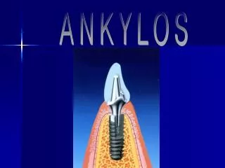
ANKYLOS. index. ANKYLOS – Surgical Procedures. index. ANKYLOS – Standard Abutment System. index. ANKYLOS – Balance Abutment System. index. ANKYLOS – SynCone Concept. ANKYLOS – Surgical Procedures. Instrument. Two-phase Handpiece-driven preparation

E N D
index ANKYLOS –Surgical Procedures
index ANKYLOS –Standard Abutment System
index ANKYLOS –Balance Abutment System
index ANKYLOS –SynCone Concept
Instrument • Two-phase • Handpiece-driven preparation • Manual preparation/final preparation
Surgical procedure • Smoothing the bone • Marking the implant position • Twist drill
Depth drill • Tri-spade drill • Low-pressure • Sub-crestal implant position
Reaming the site • Non-cutting tip • Also be handpiece-driven • Max speed • 15 rpm • Max torque • 60NCm
Measuring • Reamer top edge • Slightly below bone level • Tapping the thread
Opening the implant pack and seating the insertion tool • Attach the handle to the implant driver
Placing the implant manually • Dismantling • Remove the retaining screw
Suture • Transgingiva healing • Sulcus former
Uncovery • Incision • Minimally invasive uncovery
Removing cover screw • Tissue punch(option)
Standard abutment sulcus former • Height • 1.5-3mm • Diameter • 3.3-4.5 • remain 14 days • Compact-standard
compact • Standard • Cover screw remaining
Option • Membrane screw for GBR
Concept • ANKYLOS implant system includes two abutment system based on the conical connector • Standard abutment system • Balance abutment system • Main difference • Technique for transferring the implant position to the lab. • Abutment level impression • Implant level impression
Abutments for chairside selection • Placed prior to impression • Superstructure is fabricated on implant analog • Tapering sulcus section provides for a maximum amount of tissue and firm gingiva • Vertical groove prevents the crown from rotating • Conical connector provides for bacteria proof, anti-rotation • Superstructure can be screw-retained or cemented
Straight abutment • One-component abutment • Used for single crown • Retained with an occlusal screw • 25 Ncm torque
15° preangled abutment • Two-component abutment (with central straining screw) • Superstructure retained with a lateral screw • 15 Ncm torque
Torque • Sulcus former • 6 NCm • Straight abutment • 25 NCm • 15° abutment • 15 NCm • Screw-retained superstructure • 10 NCm
Clinical procedure • Recovering the implant
Inserting a compact sulcus former • Emergence height from 1.5 to 6.0(1.5,3.0,4.5,6.0,) • Torque-6 NCm • Removing the sulcus former • After healing period(10-14 days)
Optional procedure • Inserting a standard sulcus former • Cover screw must not be removed
Inserting a straight abutment • 25 NCm • Headless screw shoud be screwed until the superstructure is placed • Prechilled to prevent rotation • 2-3 brief burst of spray at intervals of 5 seconds • Use cooling device
Inserting a preangled abutment • Hold the desired direction with the positioning key • 15 NCm
Fitting the impression cap • Integral retainer • Preangled abutment • Flat side of impression cap must be positioned atop the lateral thread
Impression taking • Transfer • Pick-up
Temporary restorarion • Use plastic temporary cap • Fabricated from a vacuum-formed template taken of the diagnostic wax-up
Superstructure • Following technical section
Crown retained with an occlusal screw(straight abutment) • Unscrew the headless screw • 10 NCm
Cemented crown • Straight • Headless screw • Angled • Gutta percha,cotton..
Model fabrication,solely implant-supported • Shortened groove for 15° abutment • Prior to the model fabrication, the undercut neck area of analog must be blocked out with wax • Position the analog
Gingiva mask • model
Two-piece analog • Seal the underside of the laboratory sleeve with wax to protect it against stone • For the preparation of a saw-cut model the abutment analog and the sleeve must be shortened below the notch
Model fabrication, tooth-/implant-supported • Position analog • Gingiva mask
Pouring with type IV super stone • Sawing out the model
Prepare removable die • Handle for analog • When one-piece analog are used, a second analog is required
Implant supported bridge,screw-retained • Mounting • Remove gingiva mask for good view
Placing wax-up coping • Length marked • Shortening of the wax-up screw