Download
1 / 47
470 likes | 489 Views
Follow these steps to design and assemble a propeller plane in your CAD software. Learn how to add components, fix them in place, and rotate them as needed. Save your drawing and customize colors for a personalized touch.

E N D
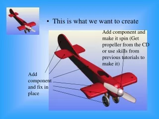
Add component and make it spin (Get propeller from the CD or use skills from previous tutorials to make it) • This is what we want to create Add component and fix in place
Open each part you plan to use • Check there are no other objects in the files • If there are use the object selector to select them, they will go red • Press delete to remove them • Save the changed file.
Now create a new design as follows • Click on file • Open a new design
Select wing • Click on open
Click on the object selector • Click on the wing so it goes red • Click and hold down the left button, drag the wing to the side
Go to assembly • Select add component • Select wheel support • Click open
Click on the object selector • Click on the support so it goes red • Click and hold down the left button, drag the support to the side
Go to assembly • Select add component • Select wheel support again • Click open.
Rotate the view using the arrows • Select one of the supports by clicking on it • Hold down the left button and move the support so it sits on the wing rectangle. (use shift – Z to zoom in and make it easier)
Rotate the drawing • Reposition the supports in this direction
Rotate the drawing through 180 degrees • Select and move the other support Use shift – Z and shift – H to make this easier
Rotate the drawing using the arrows and check nothing has moved
Select the wing using the object selector, click once • Right click with the mouse once on the wing • Select fix component from the menu. The wing will now be rigidly fixed in the drawing and cannot be moved
Select each support in turn • Right click on each • Select fix component.
Select assembly • Select add component • Select body • Click on open
Rotate the drawing • Select the body and move it until it is central. Click once to select then click and hold to move it
Rotate the drawing and check the other side • Reposition the body until none of the wing structure is showing
Select the body by clicking once • Right click on it • Select fix component
Go to assembly • Select add component • Select tail • Click on open
Rotate the drawing so you are above the plane • Use autoscale to see the body and tail • Select and drag the tail so it is central on the body.
Once you are sure the position is correct click once on the tail then right click on the tail and select fix component
Select assembly • Select add component • Select rudder • Click on open
View the drawing from the side • Use shift – Z to zoom in on the tail
Rotate the drawing and view it from above • Select the rudder • Reposition it over the rear.
Select the rudder by clicking once • Right click on it • Select fix component
Select assembly • Select add component • Select wheel • Click on open
Move the first wheel • Insert another wheel • Rotate the drawing • Select one of the wheels and begin moving it to position.
Rotate the drawing • Select the wheel • Click zoom to object
Rotate the drawing and move the wheel if needed • Select the wheel, right click and fix it in place • Zoom out and repeat on the other wheel.
Select assembly • Select add component
Select prop • Click open to put it in the drawing
Click on the edge selector • Select the edge of the propellers flat surface • Hold down shift and select the edge of the large body circle as well as the propeller circle.
Select the assembly menu • Click on the centre axes option
Rotate the design • Click on the object selector • Click on the propeller, click again and hold down the left button, drag the propeller out of the plane
Click on the surface selector • Select the end of the plane body • Press shift and select the flat face of the propeller.
If this spins the propeller around go straight to undo without pressing anything, repeat the procedure but select align • Select the assembly menu • Click mate
Select the object selector • Click on the propeller then click and hold the left button down • Moving the propeller should now make it turn
To change the colour of the plane, click on it once then right click on it. • Select set component colour
Choose the colour you want and add it to the custom colours if you are going to use it for other bits