DC Machines in Electrical Engineering
650 likes | 681 Views
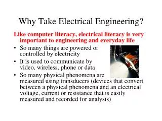
Explore the principles, construction, and characteristics of DC motors and generators in electrical engineering. Learn about the advantages and applications of DC machines.

DC Machines in Electrical Engineering
E N D
Presentation Transcript
Electrical Engineering Technology ELECTRICAL ENGINEERING TECHNOLOGYEMT 113/4 Semester II 08/09 CHAPTER 2: DC MACHINES
Electrical Engineering Technology SUBTOPICS • Introduction to DC Machines • DC motors : Principles of Operation, equivalent circuit & Characteristics • DC generators : Principles of operation, equivalent circuit & Characteristics Semester II 08/09
Electrical Engineering Technology INTRODUCTION TO DC MACHINES Semester II 08/09
Electrical Engineering Technology WHAT ARE DC MACHINES? • DC generators that convert mechanical energy to DC electric energy. • DC motors that convert DC electric energy to mechanical energy. Semester II 08/09
Electrical Engineering Technology • DC Machine is most often used for a motor. • DC motors are found in many special • industrial environments. Motors drive • many types of loads from fans and • pumps to presses and conveyors • Advantages of dc machines : easy speed and torque regulation. • However, their application is limited to mills, mines and trains. As examples, trolleys and underground subway cars may use dc motors. • In the past, automobiles were equipped with dc dynamos to charge their batteries. Semester II 08/09
Electrical Engineering Technology • Important parts: • - STATOR : provides mechanical support for the machine, consists poles and yoke • - ROTOR / ARMATURE : the rotating part, shrouded by fixed poles on the stator • COMMUTATOR : mechanical rectifier, which changes the AC voltage of the rotating conductors to DC voltage • BRUSHES : conduct the current from the commutator to the external circuit • WINDINGS • uniform magnetic flux is established by fixed poles mounted on the inside of the stationary number called STATOR • May use permanent magnet as poles or wind the field windings (excitation coils) around the poles • Advantage of wound machine: easy to control the flux in the machine by regulating the direct current in the field winding Semester II 08/09
Electrical Engineering Technology DC machines, like other electromechanical energy conversion devices have two sets of electrical windings: • field windings - on stator • amarture windings - on the rotor. Semester II 08/09 DC motor stator with poles visible Rotor of a dc motor
Electrical Engineering Technology DC Machines Construction • The stator of the dc machine has poles, which are excited by dc current to produce magnetic fields. • In the neutral zone, in the middle between the poles, commutating poles are placed to reduce sparking of the commutator. The commutating poles are supplied by dc current. • Compensating windings are mounted on the main poles. These short-circuited windings damp rotor oscillations. Semester II 08/09
Electrical Engineering Technology • The poles are mounted on an iron core that provides a closed magnetic circuit. • The motor housing supports the iron core, the brushes and the bearings. • The rotor has a ring-shaped laminated iron core with slots. • Coils with several turns are placed in the slots. The distance between the two legs of the coil is about 180 electric degrees. Semester II 08/09
Electrical Engineering Technology • The coils are connected in series through the commutator segments. • Ends of each coil are connected to a commutator segment. • Commutator consists : insulated copper segments mounted on an insulated tube. • Two brushes are pressed to the commutator to permit current flow. • Brushes are placed in the neutral zone, where the magnetic field is close to zero, to reduce arcing. Semester II 08/09
Electrical Engineering Technology • The commutator switches the current from one rotor coil to the adjacent coil • The switching requires the interruption of the coil current. • The sudden interruption of an inductive current generates high voltages . • The high voltage produces flashover and arcing between the commutator segment and the brush. Semester II 08/09
Electrical Engineering Technology Equivalent Circuit The brush voltage drop RA Semester II 08/09 External variable resistor used to control the amount of current in the field circuit Armature circuit (entire rotor structure) Equivalent circuit of dc motor Field Coils NOTE: Because a dc motor is the same physical machine as a dc generator, its equivalent circuit is exactly the same as generator except for the direction of current flow.
Electrical Engineering Technology DC MOTORS : Principles of Operation, equivalent circuit & Characteristics Semester II 08/09
Electrical Engineering Technology Introduction TYPES OF DC MOTOR • Five major types of DC motors: • Separately excited DC motor • Shunt DC motor • Permanent Magnet DC motor • Series DC motor • Compounded DC motor • classified according to electrical connections of armature windings and field windings. Semester II 08/09
Electrical Engineering Technology • ARMATURE winding : the winding which a voltage is induced. • FIELD windings : the windings that produce the main flux in the machines. • The magnetic field of the field winding is approximately sinusoidal, thus AC voltage is induced in the armature winding as the rotor turns under the magnetic field of stator. • The COMMUTATOR and BRUSH combination converts the AC generated voltages to DC. Semester II 08/09
Electrical Engineering Technology DC Motor Operation To understand the operation of a DC motor, we need to know the basic mechanism of the DC Motor – The Electromagnetism. Semester II 08/09 LETS REVIEW..!!
Electrical Engineering Technology Review of Magnetism Lines of flux define the magnetic field and are in the form of concentric circles around the wire. The magnetic lines around a current carrying conductor leave from the N-pole and re-enter at the S-pole. Semester II 08/09 "Left Hand Rule" states that if you point the thumb of your left hand in the direction of the current, your fingers will point in the direction of the magnetic field.
Electrical Engineering Technology Semester II 08/09 The poles of an electro-magnetic coil change when the direction of current flow changes.
Electrical Engineering Technology • The motor has a definite relationship between the direction of the magnetic flux, the direction of motion of the conductor or force, and the direction of the applied voltage or current. • Fleming's left hand rule can be used: • - thumb will indicate the direction of motion • - forefinger will indicate the direction of the magnetic field • - middle finger will indicate the direction of current. Semester II 08/09 • In either the motor or generator, if the directions of any two factors are known, the third can be easily determined.
Electrical Engineering Technology Equivalent Circuit The brush voltage drop RA Semester II 08/09 External variable resistor used to control the amount of current in the field circuit Armature circuit (entire rotor structure) Equivalent circuit of dc motor Field Coils NOTE: Because a dc motor is the same physical machine as a dc generator, its equivalent circuit is exactly the same as generator except for the direction of current flow.
Electrical Engineering Technology Simplified Equivalent Circuit Semester II 08/09 Simplified quivalent circuit of dc motor • The brush drop voltage (Vbrush )is often only a very tiny fraction of the generated voltage in the machine – Neglected or included in RA. • Internal resistance of the field coils is sometimes lumped together with the variable resistor and called RF
Electrical Engineering Technology The Magnetization Curve of a DC machine • The internal generated voltage in the motor • From the equation, • EA is directly proportional to the flux () in the motor and speed of the motor (). • The field current (IF) in DC machines produces a field magnetomotive force (mmf) • This magnetomotive force (mmf) produces a flux() in the motor in accordance with its magnetization curve. Semester II 08/09 IF mmf flux
The magnetization curve of a dc machine expresses as a plot of EA versus IF, for a fixed speed ω0 Electrical Engineering Technology • Since the field current (IF) is directly proportional to magnetomotive force (mmf) and • EA is directly proportional to the flux, the magnetization curve is presented as a plot EA versus field current for a given speed. Semester II 08/09 • The induced torque developed by the motor is given as NOTE : To get the maximum possible power, the motors and generators are designed to operate near the saturation point on the magnetization curve (at the knee of the curve).
Electrical Engineering Technology DC Motor Operation • DC MOTOR OPERATION FLOWS: • Uniform magnetic field is created by poles • The armature conductors are forces to carry current by connecting them to DC power source • The current direction in the conductors under each pole is kept the same by commutator • According to Lorentz force equation, a current carrying conductor when placed in a magnetic field experiences a force that tends to move it • All conductors placed on the periphery of a DC motor are subjected to the forces • These forces cause armature to rotate in the direction of the torque developed by the motor. Semester II 08/09
Electrical Engineering Technology DC Motor Operation Semester II 08/09
Electrical Engineering Technology DC Motor Operation : Current Semester II 08/09
Electrical Engineering Technology DC Motor Operation : Force Semester II 08/09
Electrical Engineering Technology DC Motor Operation : Magnetic Field Semester II 08/09
Electrical Engineering Technology Basic principle of operation • The generated voltage of a DC machines having (p) poles and (Z) conductors on the armature with (a) parallel path between brushes as below : where K = pZ /(2πa) = machine constant Semester II 08/09 • The mechanical torque which also equal to electromagnetic torque, is found as follows: • In the case of a generator: • m is the input mechanical torque, (converted to electrical power) • For the motor: • e is developed electromagnetic torque, (drive the mechanical load)
Electrical Engineering Technology • The induced or generated DC voltage (EA) appearing between the brushes is a function of the field current (IF) and the speed of rotation () of the machine. This generated voltage is : Where K’ = voltage constant = rotation per mina Semester II 08/09 • If the losses of the DC machine are neglected, the electrical power is equal to the mechanical power
Electrical Engineering Technology Important Notice Equation of Induced Voltage when speed, n (revolution per minute/ Run per minute/ rotation per minute (rpm) Equation of Induced voltage when speed, w (in radian per second / Angular speed) Semester II 08/09 Where p : no of poles z : no of conductors a : no of current path Where p : no of poles z : no of conductors a : no of current path
Electrical Engineering Technology Separately excited DC motor Semester II 08/09 Separately excited motor is a motor whose field current is supplied from a separate constant-voltage power supply.
Electrical Engineering Technology Shunt DC motor Semester II 08/09 A shunt dc motor is a motor whose field circuit get its power directly across the armature terminals of the motor.
Electrical Engineering Technology Shunt DC Motor : Terminal Characteristics • Consider the DC shunt motor. From the Kirchoff’s Law • Induced Voltage Semester II 08/09 • Substituting the expression for induced voltage between VT and EA. • Since, then current IA can be expressed as
Electrical Engineering Technology • Finally, solving for the motor's speed yield This equation is a straight line with a negative slope. Semester II 08/09 Torque-speed characteristic of a shunt or separately excited dc motor
Electrical Engineering Technology Shunt DC Motor : Terminal Characteristic • Affect of Armature Reaction (AR) will reduce flux as the load increase (indalso increase), so it will increase motor speed (). => • If the motor has compensating winding, the flux () will be constant. Semester II 08/09 Torque-speed characteristic of a motor with armature reaction present.
Electrical Engineering Technology Shunt DC Motor : Speed Control 1 : Changing The Field Resistance to decrease. • Increasing RF causes IF • Deceasing IF decreases . Semester II 08/09 • Decreasing lowers EA • Decreasing EA increases IA • Increasing IA increases with the change in IA dominant over the change in flux (). and the speed ω increases. • Increasing τind makes
Electrical Engineering Technology Shunt DC Motor : Speed Control • Increasing speed to increases EA = K again. • Increasing EA decreases IA. • Decreasing IA decreases until at a higher speed ω Semester II 08/09 Decreasing RF would reverse the whole process, and the speed of the motor would drop. The effect of field resistance speed control on a shunt motor’s torque speed characteristic: over the motor’s normal operating range
Electrical Engineering Technology Shunt DC Motor : Speed Control 2: Changing The Armature Voltage Armature voltage control of a shunt (or separately excited) dc motor. Semester II 08/09 • An increase in VA increases IA [= (VA – EA)/RA] • Increasing IA increases increasing ω. • Increasing τind makes • Increasing ω increases EA (=Kω )
Electrical Engineering Technology Shunt DC Motor : Speed Control • Increasing EA decreases IA [ = (VA – EA)/RA] at a higher ω. • Decreasing IA decreases τind until Semester II 08/09 The effect of armature voltage speed control on a shunt motor’s torque speed characteristic The speed control is shiftted by this method, but the slope of the curve remains constant
Electrical Engineering Technology Shunt DC Motor : Speed Control 3 : Inserting Resistor in Series with Armature Circuit Add resistor in series with RA Semester II 08/09 The effect of armature resistance speed control on a shunt motor’s torque – speed characteristic Equivalent circuit of DC shunt motor Additional resistor in series will drastically increase the slope of the motor’s characteristic, making it operate more slowly if loaded
Electrical Engineering Technology Shunt DC Motor : Speed Control Semester II 08/09 The above equation shows if RA increase, speed will decrease This method is very wasteful method of speed control, since the losses in the inserted resistor is very large. For this it is rarely used.
Electrical Engineering Technology Series DC Motor Series DC Motor: DC motor whose field windings consists of relatively few turns connected in series with armature circuit Semester II 08/09 Equivalent circuit of a series DC motor. The Kirchhoff’s voltage law equation for this motor
Electrical Engineering Technology Series DC Motor : Induced Torque • The induced or developed torque is given by • The flux in this motor is directly proportional to its armature current. Therefore, the flux in the motor can be given by Semester II 08/09 where c is a constant of proportionality. The induced torque in this machine is thus given by This equation shows, torque in the motor is proportional to the square of armature current. So, series motor givemore torque per ampere than any other dc motor, therefore it is used in applications requiring very high torque, e.g. starter motors in cars, elevator motors, and tractor motors in locomotives.
Electrical Engineering Technology Series DC Motor : Terminal Characteristic • To determine the terminal characteristic of a series dc motor, • analysis will be based on the assumption of a linear magnetization curve, and the effects of saturation will be considered in a graphical analysis • The assumption of a linear magnetization curve implies that the flux in the motor given by : Semester II 08/09 • The derivation of a series motor’s torque-speed characteristic starts with Kirchhoff’s voltage law: From the equation; thearmature current can be expressed as:
Electrical Engineering Technology • Also, EA = K, substituting these expression yields: We know ; Semester II 08/09 • Substituting the equations so the induced torque equation can written as Therefore, the flux in the series motor can be written as :
Electrical Engineering Technology • Substituting the previous equation for VTyields: Semester II 08/09 • Disadvantage of series motor can be seen immediately from this equation. When the torque on this motor goes to zero, its speed goes to infinity. • In practice, the torque can never go entirely to zero, because of the mechanical, core and stray losses that must be overcome.
Electrical Engineering Technology • However, if no other load is connected to the motor, it can turn fast enough to seriously damage itself. • NEVERcompletely unload a series motor, and NEVER connect one to a load by a belt or other mechanism that could break. Semester II 08/09 Figure : The ideal torque- speed characteristic of a series dc motor
Electrical Engineering Technology Series DC Motor : Speed Control Method of controlling the speed in series motor : • Change the terminal voltage of the motor. If the terminal voltage is increased, the speed also increased, resulting in a higher speed for any given torque. Semester II 08/09 • By the insertion of a series resistor into the motor circuit, but this technique is very wasteful of power and is used only for intermittent period during the start-up of some motor.
Compounded DC Motor series series shunt shunt A compound DC motor is a motor with both a shunt and a series field Two field windings : - One is connected in series with armature (series field) - Other is connected in parallel with the armature (shunt field). The equivalent compound DC motor a) Long-shunt connection (cumulative compounding), (b) Short-shunt connection (differential compounding)