Download
1 / 56
570 likes | 790 Views
Fault Tolerance Recovery (Week:9). Introduction (Recovery) Recovery refers to restoring a system to its normal operational state Generally, its a very complicated process Following are the issues involved in recovery: Basic causes that lead to failures and the types

E N D
Fault Tolerance Recovery (Week:9)
Introduction (Recovery) • Recovery refers to restoring a system to its normal operational state • Generally, its a very complicated process • Following are the issues involved in recovery: • Basic causes that lead to failures and the types • How a process can recover from failure when it does not interact with another process • Effects of a process failing on other processes in concurrent systems, and • Techniques to recover cooperating processes • Recovery in distributed database systems
Basic Terminologies • A system consists of a set of hardware and software components and is designed to provide a specified service. • Failure of a system occurs when the system does not perform its services in the manner specified. • An erroneous state of the system is a state which could lead to a system failure by a sequence of valid state transitions • A fault is an anomalous physical condition. • An error is a manifestation of a fault in a system, which can lead to system failure
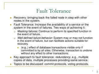
Recovery • Failure recovery is a process that restores an erroneous state to an error-free state. (after a failure, restoring system to its "normal" state) • Failure Classification • process failure • system failure • secondary storage failure • communication medium failure • Tolerating Process Failures • A failed process may be aborted or restarted from a prior state. • A wrong input in the initial stages may require a process to be aborted. • Recovering from System Failures • amnesia -- restart in predefined state • partial amnesia -- reset part of the state to predefined • pause -- roll back to before failure • halting -- give up
ToleratingSecondary Storage Failures • archiving (periodic backup) • mirroring (continuous) • activity logging • Tolerating Communication Medium Failures • ack & resend • more complex fault-tolerant algorithms • Backward Error Recovery • based on recovery points • two approaches: • operation-based recovery • state-based recovery
BACKWARD AND FORWARD RECOVERY • Forward-error recovery; Errors and damages can be completely accurately assessed and enable the system to move forward. It requires less overhead for e.g. disk read error. This technique is known as forward-error recovery. • Backward-error recovery;If the above is not possible, then the process state is restored to previous error state. It is simpler. For e.g. OS, Data, Application program etc… got corrupted. This is know as backward-error recovery. • Forward versus Backward Error Recovery • Backward error recovery is simple than forward error recovery as it is independent of the fault and the error caused by the fault. • General recovery mechanism is provided in backward error recovery while in forward error recovery it is not possible.
Backward error recovery: Basic approach • A storage that does not loose information in the event of system failure is known as stable storage. It is used to store logs and recovery points. The contents of both the secondary and stable storage survive system failure. However, contents of the stable storage are more secure than secondary storage.
Two Approaches to Fault Tolerance • operation based • record a log (audit trail) of the operations performed • restore previous state by reversing steps • state based • record a snapshot of the state (checkpoint) • restore state by reloading snapshot (rollback) • Practical systems employ a combination of the two approaches, e.g., logging with periodic full-DB snapshots for archive.
Check Pointing & Recovery • Check pointing and recovery techniques that takes a consistent set of the checkpoints and avoids livelock problems during recovery. • Technique properties • Amount of state saved: This property refers to the abstraction level used by the technique to analyze an application. It can range from seeing each application as a black box, hence storing all application data, to selecting specific relevant cores of data in order to achieve a more efficient and portable operation. • Automatization level: Depending on the effort needed to achieve fault tolerance through the use of a specific check pointing solution. • Portability: Whether or not the saved state can be used on different machines to restart the application. • System architecture: How is the check pointing technique implemented: inside a library, by the compiler or at operating system level.
Fault Tolerance… • Design issues • Process deaths, Machine Failure and Network Failure • Reliable communication • Send messages reliably among processes, communication link should be fault tolerate • Failure and replication • In case of a H/W or its part failure, alternate arrangement must be available. For e.g. replication of files on different machines. • Atomicity • Means either all the operations associated with the transaction are executed to completion or none are performed. For e.g. funds transfer in which either both the credit and debit (payment through cheque, where amount from your account is debt and credit to others) occur or neither
Fault Tolerance… • Commit • It signifies that the transaction has terminated its execution successfully for e.g. either both the credit and debit occur or neither (transaction abort). • Distributed Commit • In distributed system, it becomes much more complicated to ensure the atomicity property of a transaction as compared to in a centralize system. • This difficulty occurs because several sites may be participating in the execution of a single transaction.
Fault Tolerance…. • It is the function of the transaction coordinator of a distributed system to ensure that the execution of the various transaction in the distributed system preserves atomicity. • Each site has its own local transaction coordinator that is responsible for coordinating the execution of all the transaction initiated at that site. • The failure of one of these sites may result in erroneous computations.
Fault tolerance… • Two phase commit protocol • Protocol assumes that one of cooperating process act as coordinator • Other process as cohorts at different sites • Protocol assumes that a stable storage is available at each site and write a head protocol is active • At the beginning of the transaction, the coordinator sends a start transaction message to every cohort.
Faulty Tolerance… • Phase I. At the coordinator • Coordinator sends a COMMIT-REQUEST message to every cohort for commit • Coordinator waits for reply • At cohorts. • On Receiving COMMIT-REQUEST MESSAGE, • If the transaction is successful, it writes UNDO and REDO log on the stable storage and sends AGREED message to coordinator, otherwise ABORT message to coordinator
Fault Tolerance… • Phase II. At the coordinator • If the cohort reply AGREED and the coordinator also agrees • Coordinator writes COMMIT record into the log and also • send a commit message to all cohorts • Otherwise, ABORT message to all cohorts • the coordinator waits for acknowledgement from cohort • If acknowledgement is not received by coordinator, which resends the commit/abort message to the cohort. • If all the acknowledgements are received, coordinator writes a complete record to the log
Fault Tolerance… • At cohort • On receiving a COMMIT message, cohort releases all resources • On receiving the ABORT message a cohort UNDO the log record releases all resources.
Introduction: • A DFS (distributed file system) is a resource management component of a distributed operating system. • It implements a common file system that can be shared by all the autonomous computers in the system. • Two goals: • Network transparency • DFS provides the same functional capabilities to access files distributed over a network. • User do not have be aware of the location of files to access them. • High Availability • User should have the same easy access to file irrespective of their physical location. • System failure or regularly scheduled activities such as backup or maintenance should not result in the unavailability of files
Architecture of DFS • files can be stored at any machine and the computation can be performed at any machine • A machine needs to access a file stored on a remote machine, the remote machine performs the necessary file access operation and returns data • For higher performance, several machines referred to as file server, are dedicated to strong files and performing storage and retrieval operations. • Two services: • Name server • Cache manager
Name Server: • A name server is a process that maps names specified by client top stored objects such as files & directories . • The mapping occurs when a process reference a file or directory for the first time. • Cache Manager • A cache manger is a process that implements file caching . • A copy of data stored at a remote file server is brought to the client’s machine. • It can be present at both client s and file servers. • Cache manager at the server cache files in the main memory to reduce delays due to disk latency. • If multiple clients are allowed to cache a file and modify it, the copies can become inconsistent.
Mechanisms for building DFS • Mounting: • Allows the building together of different filename spaces to form a single hierarchically structured name space (collection of files). • A name space can be bounded to or mounted at an internal node or leaf node of a name space tree. • The kernel maintains a structure called the mount table, which maps mount points to appropriate strong device • Approach 1: Mount information is maintained at clients that is each client has to individually mount every required file system. When files are moved to a different server then mount information must be updated in mount table of every client. • Approach 2: Mount information is maintained at servers. If files are moved to a different servers, then mount information need only be updated at servers.
Caching • This mechanism is used in DFS to reduce delays in accessing of data. • In file caching, a copy of data stored at remote file server is brought to client when referenced by client so subsequent access of data is performed locally at client, thus reducing access delays due to netwrok latency. • Data can be cached in main memory or on the local disk of the clients. • Data is cached in main memory at servers to reduce disk access latency. • Need of Caching in DFS: • File system performance gets improved accessing remote disks is much slower than accessing local memory or local disks. • It also reduces the frequency of access to file servers and the communication network so scalability gets increased.
Hints • Caching results in the cache consistancy problem when multiple clients cache and modify shared data. • This problem can be avoided by great level of co-operation between file servers and clients which is very expensive. • Alternative method is to treat cached data as hints that is cached data are not expected to be completely accurate. • Only those class of applications which can recover after discovering that cached data are invalid can use this approach. • Example: After the name of file or directory is mapped to physical object, the address of object can be stored as hint in the cache. If the address is incorrect that is fails to map the object, the cached address is deleted from the cache and file server consult the same server to obtain the actual location of file or directly and updated the cache.
Bulk Data Transfer • In this mechanism, multiple consecutive data blocks are transferred from server to client. • This reduces file access overhead by obtaining multiple number of blocks with a single seek, by formatting and transmitting multiple number of large packets in single context switch and by reducing the number of acknowledgement that need to be sent. • This mechanism is used as many files are accessed in their entirety. • Encryption • This mechanism is used for security in Distributed systems. • The method was developed by Needham Schrodkar is used in DFS security. In this scheme, two entities which want to communicate establish a key for conversation with help of authentication server. • It is important to note that the conversation key is determined by the authentication server, but is never sent in plain text to either of the entities
File System: DFS Design issue and case Study (Week:11)
DFS Design issues • 1.Naming and Name Resolution • Namerefers to an object such as file or a directory.Name Resolution refers to the process of mapping a name to an object that is physical storage. Name space is collection of names.Names can be assigned to files in distributed file system in three ways: • 1. Concatenated (host : local-name); no transparency (user should know the path of the file), not location independent, means name of the file need not to be changed when the file’s physical location changes. • 2. Mount remote directories onto local directories (location transparent) • 3. Global directory; limited to one computing facility.
2.Name Server: • It is responsible for name resolution in distributed system. Generally two approaches are used for maintaining name resolution information.Way 1: Use a single name server that is all clients send their queries to single server which maps names to objects. Its limitation is: If name server fails, the entire system is affected and Name server become a bottleneck and degrades the performance of the system.Way 2: Use several name servers(on different hosts) wherein each server is responsible for mapping objects stored in different domains. This approach is generally used. Whenever a name is to be mapped to an object, the local name server is queried. The local name server may point to remote server for further mapping of the name. Example: "a/b/c"- requires a remote server mapping the /b/c part of the filename. This procedure is repeated until the name is completely resolved.
3.The Concept Of Contexts • A context identifies the name space (collection of files) in which to resolve given name • Contexts can partition a name space along geographical boundary, organizational boundary, specific to hosts, a file system type etc. • A file name can be thought of as composed of a context and a name local to that context. • X-Kernel logical file system: • It is a file system that makes use of contexts. • User defines his own file space hierarchy • Tide naming scheme: • The name space is partitioned into a set of logically independent directory tress called tide (events) trees. • Each process running in the system has a set of tide trees associated with it that constitute the process’s tide environment
4.Caches on disk or main memory • The data cached by a client should be in main memory at the client or a local disk at the client. • Advantages: • Diskless workstations can also take advantage of caching. • Accessing a cache in main memory is much faster that accessing a cache on local disk. • the server-cache is in the main memory at the server, hence a single design for a caching mechanism is applicable to both clients and server. • Disadvantages: • Client-cache in main memory is that it competes with the virtual memory system for physical memory space. • A scheme to deal with the memory contention between cache and virtual memory system is necessary . • Should also prevent data blocks from being present in both the virtual memory and the cache.
5.Writing Policy • Decides when a modified cache block at a client should be transferred to the server. • Write-through: • All writes requested by the application at client are also carried out at the servers immediately. • If the event of a client crash, little information is lost. • Delayed writing policy: • It delays the writing at the server. • Modification due to a write are reflected (copied) at the server after some delay. • Advantage is writes to the cache is much faster than disk.
Write on close policy: • Write data back to the server when the file is closed at the client. • The traffic at the server depends on the average period that files are open. • This policy does not greatly benefit from delaying the updates. • The average period for which files are open is long. • This policy is also sensitive to losing data in the event of a client crash • Advantage is more frequent flushing for files that are open for long time.
6.Cache Consistency • Server-initiated approach: • Servers inform cache managers whenever the data in the client cache become stale. • Cache manager at client can then retrieve the new data or invalidate the blocks containing the old data in their cache. • Client-initiated approach: • It is the responsibility of cache managers at the client to validate data with the server before returning it to the clients. • Both approaches are expensive and unattractive as they require elaborate cooperation between servers and cache manager. • Concurrent-writing sharing: • A file is open at multiple clients and at least one client has it open for writing. • When concurrent-write sharing occurs for a file, the file server informs all the client to purge their cached data items belonging to that file.
7.Availability: • Availability is one of the important issues in the design of distributed file system. • Replication is the primary mechanism used for enhancing the availability of files in DFS. • Replication is inherently expensive because of the extra storage space required to store the replicas and the overhead incurred in maintaining all the replicas up to date. • 8.Scalability • Scalability deals with the suitability of the design of a system to cater to the demands of a growing system. • caching which reduces network latency and server-load, is the primary technique used in client server organization to improve the client response time.
Semantics • The semantic of the file system characterized the effect of access on file. • Guaranteeing, the semantic in DFS which employ caching, is difficult and expensive. • Communication delays, invalidations may not occur immediately after updates and before reads occur at client in file system employing server-initiated cache. • All reads and writes from various clients will have to go through the server or sharing will have to be disallowed either by the server, or by the use of locks by application.
Case Study: Sun Network File System • Introduction • Network File System (NFS) is a distributed file system protocol originally developed by Sun Microsystems • user on a client computer to access files over a network in a manner similar to how local storage is accessed. • A major goal of the NFS is to keep the file system independent of the underlying hardware and the operating system • The Network File System is an open standard defined in RFCs, allowing anyone to implement the protocol.
Architecture: • The NFS uses the remote procedure call(RPC) mechanism for remote file operation. • RPC mechanism is independent of the transport protocols and new transport protocol can be used without affecting the higher level functions of the RPC mechanism. • External data representation (XDR) specification is used to describe the RPC protocols. • A file system interface called virtual file system(VFS) interface defines the procedures that operate on the file system as a whole. • VFS interface is based on a structure called a vnode. • Vnode contains a numerical designator for the file or directory that is network wide unique. • VFS interface can distinguish between local and remote file system.
Distributed Scheduling (Week:12)
Introduction • Good resource allocation schemes are needed to fully utilize the computing capacity of the DS • Distributed scheduler is a resource management component of a DOS • It focuses on judiciously and transparently redistributing the load of the system among the computers • Target is to maximize the overall performance of the system • More suitable for DS based on LANs
Motivation • A locally distributed system consists of a collection of autonomous computers connected by a local area communication network • Users submit tasks at their host computers for processing • Load distributed is required in such environment because of random arrival of tasks and their random CPU service time • There is a possibility that several computers are heavily loaded and others are idle of lightly loaded • If the load is heavier on some systems or if some processors execute tasks at a slower rate than others, this situation will occur often
Issues in Load Distribution • Load • Resource queue lengths and particularly the CPU queue length are good indicators of load • Measuring the CPU queue length is fairly simple and carries little overhead • CPU queue length does not always tell the correct situation as the jobs may differ in types • Another load measuring criterion is the processor utilization • Requires a background process that monitors CPU utilization continuously and imposes more overhead • Used in most of the load balancing algorithms
Classification of LDA • Basic function is to transfer load from heavily loaded systems to idle or lightly loaded systems • These algorithms can be classified as : • Static • decisions are hard-wired in the algorithm using a prior knowledge of the system • Dynamic • use system state information (VM image, process control block, I/O buffers and messages) to make load distributing decisions • Adaptive • special case of dynamic algorithms in that they adapt their activities by dynamically changing the parameters of the algorithm to suit the changing system state
Basic Terminologies • Load Balancing vs. Load sharing • Load sharing algorithms strive to reduce the possibility for a system to go to a state in which it lies idle while at the same time tasks contend service at another, by transferring tasks to lightly loaded nodes • Load balancing algorithms try to equalize loads at al computers • Because a load balancing algorithm transfers tasks at higher rate than a load sharing algorithm, the higher overhead incurred by the load balancing algorithm may outweigh this potential performance improvement
Preemptive vs. Non-preemptive transfer • Preemptive task transfers involve the transfer of a task that is partially executed • Preemptive transfer is an expensive operation as the collection of a task’s state can be difficult • What does a task’s state consist of? • VM image, process control block, I/O buffers and messages • Non-preemptive task transfers involve the transfer of the tasks that have not begun execution and hence do not require the transfer of the task’s state • Non-preemptive task transfers are also referred to as task placements
Components of a Load Balancing Algorithm • Transfer Policy • Sending or receiving a task at node depends on threshold T. If the load is exceeds a threshold T, then the transfer policy decides that the node is sender. Otherwise, receiver. • Selection Policy • Select the node which has increasing load and beyond the threshold T. • Location Policy • Find suitable nodes (sender or receiver) to share loads. A widely used method is polling • Another method is based on broadcasting. • Information policy • responsible for deciding when information about the states of other nodes in the system should be collected. • Three types are: Demand-Driven, Periodic, State-Change-Driven
Components of a Load Balancing Algorithm.. • Demand-driven • A node collects the state of other nodes only when it becomes either a sender or a receiver (decided by the transfer and selection policies at the node), making it suitable candidate to initiate load sharing. • Periodic • Nodes exchange load information periodically. • Periodic information policies do not adapt their activity to the system state. • State-change-driven • Nodes disseminate (spread widely)state information whenever their state changes by a certain degree. • It differs from a demand-driven policy in that it disseminates information about the state of a node, rather than collecting information about other nodes.
Stability • The two views of stability are, • The Queuing-Theoretic Perspective • A system is termed as unstable if the CPU queues grow without bound when the long term arrival rate of work to a system is greater than the rate at which the system can perform work. • The Algorithmic Perspective • If an algorithm can perform fruitless actions indefinitely with finite probability, the algorithm is said to be unstable.
Load Distributing Algorithms • Sender-Initiated Algorithms • Receiver-Initiated Algorithms • Symmetrically Initiated Algorithms • Adaptive Algorithms