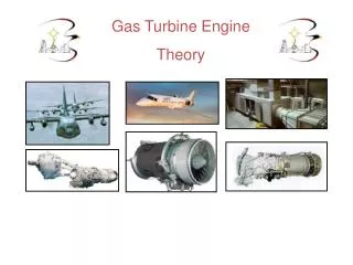
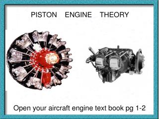
PISTON ENGINE THEORY
PISTON ENGINE THEORY. Open your aircraft engine text book pg 1-2. Piston engines ???????. Reciprocating: To move back and forth alternately. Radial engine runs on banks of cylinders arranged radially around banks the crankcase.

PISTON ENGINE THEORY
E N D
Presentation Transcript
PISTON ENGINE THEORY Open your aircraft engine text book pg 1-2
Radial engine runs on banks of cylinders arranged radially around banks the crankcase R - 4360: 3400 HP
Stationary Rotary: Gnome (click)
In-line engines Some advantages were 1) small frontal area which was better for streamlining 2)better prop clearance because the engine was inverted so the crank was at the top
V-type engines had a good (P to W ratio) because they had 2 banks of Cylinders. -During WW2 the V12 engine was one of the highest HP of any reciprocating engine. The Merlin engine had 1,650 cu of displacement and 740 hp -The Spitfire was know for its power and speed (click) Click video 2 Click video 3
The opposed engine -Most popular recip engine for light a/c and produce anywhere from 36 HP to 400 hp. -They have good P to W ratio & are streamlined because of their compact cylinder arraignment
Engine Review
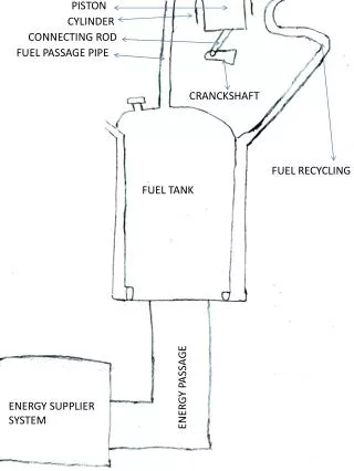
ENGINE COMPONENTS turn to pg 1-5 crankcase crankshaft connecting rod piston cylinders intake and exhaust valves
The crankcase is the foundation of the reciprocating engine
The transverse web gives great strength to the case As well as providing a place for the crankshaft bearings to be housed.
When it is bolted together instead of gaskets a mating compound is used on the flanges
The crankshaft is the backbone of the reciprocating engine-- pg 1-9 It's main job is to transfer motion from the pistons & connecting rods into the rotary motion (power) needed to turn the prop. A typical shaft has 1 or more throws which are spaced equally with each one connecting to a piston through a connecting rod
-The main journals represent the center line of the crankshaft and supports the shaft as it rotates on the main bearings. - The crankpins are usually offset from the main journals & are attachment points for the connecting rods. To save on weight these are usually hollow which also allows oil to pass through. The pins are set to correspond with engine cylinder arraignments and are at different positions in the cranking cycle as the engine rotates -The crank cheek connects the crank pin to the crank shaft . Sometimes it extends beyond the journal to act as a counterweight.}
-The crank shaft must be statically and dynamically balanced. Static means it's balanced around the center line and dynamically means balancing the centrifugal forces as it rotates. This would be similar to a tire balancing machine
A bearing is any surface that reduces friction between 2 moving parts. These can be found at the main journals the crankpins and the accessory drive shafts.
Pg 1-11---ball bearings consist of an inner and outer race with metal balls in between which allows them to handle radial and thrust loads. -roller bearings are a similar design to ball bearings except they have rollers in the middle instead of balls which makes them better for handling radial loads.
Pg 1-13 The connecting rods are the link between the crankshaft and the pistons and help transfer the power being created.. -they are usually made from a steel alloy and generally have a shape of an H or an I
-one end connects to the piston (called the piston end) and the other end is called the crankshaft end.
-There are 3 main types of RODS Plain Type Master & Articulating Fork & Blade
plain rods are used in opposed engines and are fitted to the crankshaft by a pin and cap method. To provide proper balance they are usually matched to a piston and crankpin..
Master and articulating type are most common in radial engines. There is one of these sets for every bank or row of cylinders. The master rod is the only one that actually connects the piston to the crankpin. A set of holes are machined around the crankpin end of the master rod to provide attachment points for the articulating rods. The crankpin is the only portion of the master rod that travels in a circle all the other crankipins travel in an elliptical path. Pg 1-14
The fork and blade type is used in the V type engines . It consists of a fork connecting rod which is split to allow the blade rod to attach in-between
See web site (http://www.pilotfriend.com) foranimation on crankshafts Radial Engine Crankshaft Rotary Engine In-Line , V- Type , & Opposed
A Piston is a cylindrical plunger that moves up and down in a cylinder pg 1-15
-It draws the fuel / air mixture in compresses the gas and expels the exhaust after ignition happens -also they transmit the forces produced by combustion to the crankshaft -they usually have 2 to 6 grooves on the outside that hold a set of piston rings. The area between the ring grooves are called the ring lands and the top of the piston is called the piston head.
-Pistons are usually classified by their head: FLAT , RECESSED , CUPPED , & DOMED
Pg 1-16 Piston rings preform 3 functions: 1) Prevent gas from leaking from the combustion chamber 2)Reduce oil seepage into the combustion chamber 3) transfer heat from the piston to the cylinder walls -They fit into the grooves in the piston and spring out and press against the cylinder walls
There are generally 3 different kinds of joints ( BUTT , ANGLED , OR STEPPED )
When the ring heats up it expands and the joint pushes together and seals.
These gaps must be staggered as not to allow gases to escape ( Blow By) from the combustion chamber & cause an increase in oil consumption.
-The rings in the top 2 or 3 grooves are called compression rings and the bottom 3 or 4 are called oil rings with the very bottom one being called the oil scraper. The bevel on this ring can be positioned to either put more or less oil toward the head of the piston.. The position of the cylinder will dictate this....ie if it is a bottom cylinder you want less oil toward the head but not if the cylinder is on the top of a radial engine.
Piston Pin -joins the piston head to the connecting rod pg 1-17 They are sometimes called wrist pins because they preform a similar motion to the human arm.
-Cylinders, provide a place where the burning & expansion of gases takes place to produce power. It allows a space for a piston and connecting rod to move up and down (articulating) as well as a housing for the spark plugs and valves.
pg 1-18 * Parts of a cylinder are 1) Valve Assembly. 2) Cylinder Head 3) The Barrel 4) Cooling Fins 5) Flange 6) The Skirt
The Barrel and head are heated and cooled when being assembled . When they cool they provide a gas tight seal
On the outside of the cylinder there are several cooling fins that remove the heat from the cylinder walls by having RAM air pass over the fins.
Cylinder numbering is slightly different from manufacturer to manufacturer Pg 1-21
Intake valve allows the fuel air mixture to enter the cylinder pg 1-22 Exhaust valve allows the exhaust gases to be expelled after combustion
Valve Tip Valve Stem Parts of a Valve Valve Face Valve Head
To help dissipate heat some valves are hollowed out and filled with Metallic Sodium This can reduce the operating temperature of the valve by up to 400F
Valve Seat - piece of hardened material that provides a uniform seating surface for the valve face
Because aircraft engine’s are subjected to vibrations two valve springs are used to keep the valves closed and not effected by VALVE SURGE or VALVE FLOAT This is when the spring vibrates and loses it’s ability to keep the valve closed
The camshaft is powered by the crankshaft and is control of opening and closing the valves at the appropriate time Pg 1-24 Cam lobe
The rocker arm pushes down on the valve (overcoming spring pressure) opening the valve It pivots here Push rod pushes up on one side of the rocker arm Cam lobe moves the push rod Camshaft is driven from the crankshaft through a gear