Download
1 / 25
250 likes | 411 Views
Beam-Beam Simulation for PEP-II. Yunhai Cai January 18, 2006 Machine Advisory Committee Meeting at SLAC. Acknowledgment Beam-beam task force: John Seeman (co-chair, PEP-II, SLAC) Uli Wienands (PEP-II, SLAC) Kiran Sonnad (PEP-II, SLAC) Franz-Josef Decker (PEP-II, SLAC)

E N D
Beam-Beam Simulation for PEP-II Yunhai Cai January 18, 2006 Machine Advisory Committee Meeting at SLAC
Acknowledgment Beam-beam task force: John Seeman (co-chair, PEP-II, SLAC) Uli Wienands (PEP-II, SLAC) Kiran Sonnad (PEP-II, SLAC) Franz-Josef Decker (PEP-II, SLAC) Witold Kozanecki (PEP-II, BaBar) MIA model and nonlinear map: Yiton Yan (ARDA, SLAC) Benchmark codes: Kazuhito Ohmi (KEKB) Masafumi Tawada (KEKB) Joe Rogers (CESR, Cornell) Outline Introduction Crossing angle experiments Low specific luminosity Peak luminosity: 1034 cm-2s-1, last October Effects of linear optical errors Projected luminosity Future plan
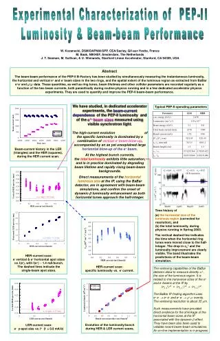
Simulation Tools • Self-consistent and strong-strong code running on a parallel PC cluster at SLAC • Include crossing angle and parasitic collisions • Benchmarked to many beam-beam experiments at PEP-II • Benchmarked against KEKB code at both the current operating condition and super-B parameters • Being used to optimize the PEP-II operation
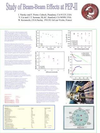
Crossing Experiments at PEP-II geometric • Simulation was carried out prior to the experiments to make sure there was enough sensitivity. • ‘By-4’ bunch pattern to avoid parasitic collision (30 sx- separation). • The orbit bump used to change the angle. The knob was carefully calibrated against a pair of BPMs next to the IP. • Luminosity feedbacks were on to align beams transversely after each change. • Tune changes were necessary to compensate the optical errors introduced from the nonlinearity of the fringe field and magnets inside the bumps.
Experiment of Crossing Angle and Parasitic Collisions measurement • ‘By-2’ bunch pattern was used to include parasitic collisions (3.2 mm or 11sx- nominal separation) • Crossing angle and the separation of parasitic collisions are related: dx = dx0 -2qsc. The corresponding range of separation is 3.6 to 2.7 mm. • Both simulation and experiment showed small nonzero crossing angle are preferred to move away from the parasitic collisions. • It is not clear why the optimum luminosity is actually better when both parasitic collisions and crossing angle are present than the head-on collision without the parasitic collision. No parasitic with parasitic
Developed a Link between MIA and LEGO • Load the fitted dK1 values to LEGO to reconstruct the optics models • Steer x and y orbits to the design orbits with a residual difference at 100 microns level • Move all sextupoles to compensate the optical effects due to the residual orbit • Achieved a good agreement between MIA and LEGO • Use LEGO to compute equilibrium beam distribution and emittances
Horizontal Dispersion Knob • Dispersion is not fitted in MIA. Good agreement between the measurement and model was a pleasant surprise • A dispersion knob based on 24 asymmetric horizontal orbit bumps was built to adjust horizontal emittance in the LER • The knob was used during a normal delivery shift. We gained a few percent of luminosity at a half value of the knob. The setting was left in the machine. • Later, individual asymmetric horizontal orbit bumps played very important role in achieving the peak luminosity by our operation colleagues as the beam current increased
A Strategy to Improve the Luminosity MIA(YY) PEP-II collider MS,JT LEGO(YC) FJD,YC BBI(YC) Model based and adiabatic correction scheme for luminosity improvement. Tuning was done during the delivery and guided by the luminosity reading.
Peak Luminosity October 10, 2005(I+=2940mA, I-=1733mA, nb=1732) beam-beam parameters: Data taken in the history buffer for a 24 hours period. The simulation used an approximately fixed current ratio.
Specific Luminosity October 10, 2005(I+=2940mA, I-=1733mA, nb=1732) Data taken in the history buffer for a 24 hours period. The simulation used an approximately fixed current ratio.
Definition of Coupling Parameters Given one-turn matrix M, we can decouple it with a symplectic transformation: where u1 and u2 can be parameterized as if no coupling case and w is a symplectic matrix: We have det(w)=1. There are ten independent parameters. Bar notes symplectic conjugate.
Luminosity Degradation due to Coupling at the IP (s=sinf) sW11=0.012 sW12=0.003 (m) sW21=1.0 (m-1) sW22=0.15
Beam Size at the Interaction Point In general coupled lattice, we have • where a,b,g are Courant-Snyder parameters in the eigen modes, w11,w12,w22,f are four coupling parameters, and e is eigen emittance. • In an electron storage ring, usually e1>>e2 • e1 and e2 are invariant in a ring. • w21 does not appear in the beam size directly. • Most time, a1=0, b1<1.0, the most sensitive parameter to luminosity is w12.
MIA/LEGO Models on October 4, 2005 (s=sinf) • High energy ring: sw11 = 1.27x10⁻², sw12 = 8.48x10⁻³ sw21 = -0.924, sw22 = 0.262 • Low energy ring: sw11 = 6.13x10⁻³, sw12 = 1.50x10⁻² sw21 = -2.07, sw22 = -0.82 • Luminosity was reduced by a factor of two if we used these coupling values in the simulation • Final empirical tuning based on the luminosity monitor by our operation colleagues are very important to reach the high luminosity
Underline Assumptions for the Projected Luminosity: 2E34 cm-2s-1 • HER 900 lattices to lower momentum compaction factor and beam emittance • Low-beta optics near by* = 8 mm • Use wiggler in the LER as a damping wiggler • More RF stations in the HER, LER? • More currents 4000/2200 mA in the machine • Shorten the bunch length to 9 mm • Adequate dynamic aperture to ensure a good beam-beam lifetime
Projected Luminosity in 2007 Simulated by Kiran Sonnad
Projected Luminosity: 2E34 cm-2s-1 Simulated by Kiran Sonnad
Future Plan • Build coupling knobs at the interaction point and calibrate them with experiments • Study a scheme of using a magnetic wire to compensate parasitic collisions • Implement nonlinear errors into the beam-beam code including chromatic effects • Reliably calculate both beam-beam lifetime and luminosity
Conclusion • A link from MIA to LEGO has been developed to make a complete machine model, including beam parameters and nonlinear effects • Along with the optics models, beam-beam simulation have been judicially applied to improve the PEP-II luminosity with some successes • The peak luminosity 1E34 cm-2s-1 is reproduced with a good accuracy by the simulation using the input parameters generated by the optics models • Linear optics errors are implemented in BBI code. The simulation showed at the coupling errors at the interaction point could significantly reduce the luminosity. The simulation indicates that the coupling at the IP in our models could not achieve the accuracy required for high luminosity • A set of consistent machine and beam parameters were optimized with simulation to achieve luminosity of 2E34 cm-2s-1 in 2007