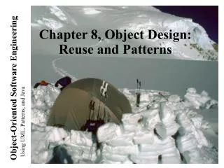
Chapter 5, Analysis: Dynamic Modeling
Chapter 5, Analysis: Dynamic Modeling. Outline. Dynamic modeling Sequence diagrams State diagrams Using dynamic modeling for the design of user interfaces Analysis example Requirements analysis document template. Example of use case format. Use case name ReportEmergency Entry condition

Chapter 5, Analysis: Dynamic Modeling
E N D
Presentation Transcript
Outline • Dynamic modeling • Sequence diagrams • State diagrams • Using dynamic modeling for the design of user interfaces • Analysis example • Requirements analysis document template
Example of use case format Use case name ReportEmergency Entry condition 1. The FieldOfficer activates the “Report Emergency” function of her terminal. Flow of events 2. FRIEND responds by presenting a form to the officer... 3. The FieldOfficer fills the form.... 4. The Dispatcher reviews the information submitted by the FieldOfficer ... Exit condition 5. The FieldOfficer receives the acknowledgment and the selected response.
How do you find classes? • From previous lectures • Application domain analysis: Talk to client to identify abstractions • Apply general world knowledge and intuition • Scenarios • Natural language formulation of a concrete usage of the system • Use Cases • Natural language formulation of the functions of the system • Textual analysis of problem statement (Abbot) • From this lecture • Dynamic model • Events: Candiates for operations to be offered by classes • Sequence diagrams as sources for objects • From future lectures • Design Patterns
Dynamic Modeling with UML • Diagrams for dynamic modeling • Interaction diagrams describe the dynamic behavior between objects • Statecharts describe the dynamic behavior of a single object • Interaction diagrams • Sequence Diagram: • Dynamic behavior of a set of objects arranged in time sequence. • Good for real-time specifications and complex scenarios • Collaboration Diagram : • Shows the relationship among objects. Does not show time • State Charts: • A state machine that describes the response of an object of a given class to the receipt of outside stimuli (Events). • Activity Diagram: • Special type of statechart where all states are action states
Dynamic Modeling • Definition of dynamic model: • A collection of multiple state chart diagrams, one state chart diagram for each class with important dynamic behavior. • Purpose: • Detect and supply methods for the object model • How do we do this? • Start with use case or scenario • Model interaction between objects => sequence diagram • Model dynamic behavior of single objects => statechart diagram
Start with Flow of Events from Use Case • Flow of events from “Dial a Number” Use case: • Caller lifts receiver • Dail tone begins • Caller dials • Phone rings • Callee answers phone • Ringing stops • ....
What is an Event? • Something that happens at a point in time • Relation of events to each other: • Causally related: Before, after, • Causally unrelated: concurrent • An event sends information from one object to another • Events can be grouped in event classes with a hierarchical structure. ‘Event’ is often used in two ways: • Instance of an event class: “New IETM issued on Thursday September 14 at 9:30 AM”. • Event class “New IETM”, Subclass “Figure Change” • Attribute of an event class • IETM Update (9:30 AM, 9/14/99) • Car starts at ( 4:45pm, Monroeville Mall, Parking Lot 23a) • Mouse button down(button#, tablet-location)
Sequence Diagram • From the flow of events in the use case or scenario proceed to the sequence diagram • A sequence diagram is a graphical description of objects participating in a use case or scenario using a DAG notation • Relation to object identification: • Objects/classes have already been identified during object modeling • Objects are identified as a result of dynamic modeling • Heuristic: • An event always has a sender and a receiver. Find them for each event => These are the objects participating in the use case
An Example • Flow of events in a “Get SeatPosition” use case : 1. Establish connection between smart card and onboard computer 2. Establish connection between onboard computer and sensor for seat 3. Get current seat position and store on smart card • Which are the objects?
Sequence Diagram for “Get SeatPosition” Seat Onboard Computer Smart Card • 1. Establish connection between smart card and onboard computer • 2. Establish connection between onboard computer and sensor for seat • 3. Get current seat position and store on smart card Establish Connection Establish Connection Accept Connection Accept Connection Get SeatPosition “500,575,300”
Heuristics for Sequence Diagrams • Layout: • 1st column: Should correspond to the actor who initiated the use case • 2nd column: Should be a boundary object • 3rd column: Should be the control object that manages the rest of the use case • Creation: • Control objects are created at the initiation of a use case • Boundary objects are created by control objects • Access: • Entity objects are accessed by control and boundary objects, • Entity objects should never call boundary or control objects: This makes it easier to share entity objects across use cases and makes entity objects resilient against technology-induced changes in boundary objects.
Is this a good Sequence Diagram? Seat Onboard Computer Smart Card • Did the modeler follow the heuristics? Establish Connection Establish Connection Accept Connection Accept Connection Get SeatPosition “500,575,300”
UML Statechart Diagram Notation Event trigger With parameters • Notation based on work by Harel • Added are a few object-oriented modifications • A UML statechart diagram can be mapped into a finite state machine State1 State2 Event1(attr) [condition]/action do/Activity Guard condition entry /action exit/action Also: internal transition and deferred events
Statechart Diagrams • Graph whose nodes are states and whose directed arcs are transitions labeled by event names. • Distinguish between two types of operations: • Activity: Operation that takes time to complete • associated with states • Action: Instantaneous operation • associated with events • associated with states (reduces drawing complexity): Entry, Exit, Internal Action • A statechart diagram relates events and states for one class • An object model with a set of objects has a set of state diagrams
State • An abstraction of the attribute of a class • State is the aggregation of several attributes a class • Basically an equivalence class of all those attribute values and links that do no need to be distinguished as far as the control structure of the system is concerned • Example: State of a bank • A bank is either solvent or insolvent • State has duration
Example of a StateChart Diagram coins_in(amount) / set balance Collect Money Idle coins_in(amount) / add to balance cancel / refund coins [item empty] [select(item)] [change<0] do: test item and compute change [change>0] [change=0] do: dispense item do: make change
Nested State Diagram • Activities in states are composite items denoting other lower-level state diagrams • A lower-level state diagram corresponds to a sequency of lower-level states and events that are invisible in the higher-level diagram. • Sets of substates in a nested state diagram denoting a superstate are enclosed by a large rounded box, also called contour.
Example of a Nested Statechart Diagram coins_in(amount) / set balance Collect Money Idle coins_in(amount) / add to balance cancel / refund coins [item empty] [select(item)] [change<0] Superstate do: test item and compute change [change>0] [change=0] do: dispense item do: make change
Expanding activity “do:dispense item” ‘Dispense item’ as an atomic activity: [change=0] do: dispense item ‘Dispense item’ as a composite activity: do: push item off shelf do: move arm to column do: move arm to row Arm ready Arm ready
Superstates • Goal: • Avoid spaghetti models • Reduce the number of lines in a state diagram • Transitions from other states to the superstate enter the first substate of the superstate. • Transitions to other states from a superstate are inherited by all the substates (state inheritance)
Modeling Concurrency Two types of concurrency 1. System concurrency • State of overall system as the aggregation of state diagrams, one for each object. Each state diagram is executing concurrently with the others. 2. Object concurrency • An object can be partitioned into subsets of states (attributes and links) such that each of them has its own subdiagram. • The state of the object consists of a set of states: one state from each subdiagram. • State diagrams are divided into subdiagrams by dotted lines.
Example of Concurrency within an Object Splitting control Synchronization Emitting Do: Dispense Cash taken Cash Ready Setting to r eset Up Ready Do: Eject Card Card taken
State Chart Diagram vs Sequence Diagram • State chart diagrams help to identify: • Changes to objects over time • Sequence diagrams help to identify • The temporal relationship of between objects over time • Sequence of operations as a response to one ore more events
Dynamic Modeling of User Interfaces • Statechart diagrams can be used for the design of user interfaces • Also called Navigation Path • States: Name of screens • Graphical layout of the screens associated with the states helps when presenting the dynamic model of a user interface • Activities/actions are shown as bullets under screen name • Often only the exit action is shown • State transitions: Result of exit action • Button click • Menu selection • Cursor movements • Good for web-based user interface design
Navigation Path Example (15-499 Spring 96) • Diagnostics • User can move cursor to Control Panel or Graph • Graph • User can select data group and type of graph • Control panel • User can select functionality of sensors • Selection • User selects data group • Field site • Car • Sensor group • Time range • User selects type of graph • time line • histogram • pie chart • Define • User defines a sensor event • from a list of events • Disable • User can disable a sensor event from a list of sensor events • Enable • User can enable a sensor event from a list of sensor events • List of events • User selects event(s) • Visualize • User views graph • User can add data groups for being viewed • List of sensor events • User selects sensor event(s) • Link • User makes a link (doclink)
Practical Tips for Dynamic Modeling • Construct dynamic models only for classes with significant dynamic behavior • Avoid “analysis paralysis” • Consider only relevant attributes • Use abstraction if necessary • Look at the granularity of the application when deciding on actions and activities • Reduce notational clutter • Try to put actions into state boxes (look for identical actions on events leading to the same state)
Summary: Requirements Analysis Functional Modeling • 1. What are the transformations? • Create scenarios and use case diagrams • Talk to client, observe, get historical records, do thought experiments • 2. What is the structure of the system? • Create class diagrams • Identify objects. What are the associations between them? What is their multiplicity? • What are the attributes of the objects? • What operations are defined on the objects? • 3. What is its control structure? • Create sequence diagrams • Identify senders and receivers • Show sequence of events exchanged between objects. Identify event dependencies and event concurrency. • Create state diagrams • Only for the dynamically interesting objects. Object Modeling Dynamic Modeling
Let’s Do Analysis 1. Analyze the problem statement • Identify functional requirements • Identify nonfunctional requirements • Identify constraints (pseudo requirements) 2. Build the functional model: • Develop use cases to illustrate functionality requirements 3. Build the dynamic model: • Develop sequence diagrams to illustrate the interaction between objects • Develop state diagrams for objects with interesting behavior 4. Build the object model: • Develop class diagrams showing the structure of the system
Power is turned on Car moves forward and car headlight shines Power is turned off Car stops and headlight goes out. Power is turned on Headlight shines Power is turned off Headlight goes out. Power is turned on Car runs backward with its headlight shining. Power is turned off Car stops and headlight goes out. Power is turned on Headlight shines Power is turned off Headlight goes out. Power is turned on Car runs forward with its headlight shining. Problem Statement: Direction Control for a Toy Car
Find the Functional Model: Do Use Case Modeling • Use case 1: System Initialization • Entry condition: Power is off, car is not moving • Flow of events: • Driver turns power on • Exit condition: Car moves forward, headlight is on • Use case 2: Turn headlight off • Entry condition: Car moves forward with headlights on • Flow of events: • Driver turns power off, car stops and headlight goes out. • Driver turns power on, headlight shines and car does not move. • Driver turns power off, headlight goes out • Exit condition: Car does not move, headlight is out
Use Cases continued • Use case 3: Move car backward • Entry condition: Car is stationary, headlights off • Flow of events: • Driver turns power on • Exit condition: Car moves backward, headlight on • Use case 4: Stop backward moving car • Entry condition: Car moves backward, headlights on • Flow of events: • Driver turns power off, car stops, headlight goes out. • Power is turned on, headlight shines and car does not move. • Power is turned off, headlight goes out. • Exit condition: Car does not move, headlight is out. • Use case 5: Move car forward • Entry condition: Car does not move, headlight is out • Flow of events • Driver turns power on • Exit condition: • Car runs forward with its headlight shining.
Use Case Pruning • Do we need use case 5? • Use case 1: System Initialization • Entry condition: Power is off, car is not moving • Flow of events: • Driver turns power on • Exit condition: Car moves forward, headlight is on • Use case 5: Move car forward • Entry condition: Car does not move, headlight is out • Flow of events • Driver turns power on • Exit condition: • Car runs forward with its headlight shining.
Find the Dynamic Model: Create sequence diagram • Name: Drive Car • Sequence of events: • Billy turns power on • Headlight goes on • Wheels starts moving forward • Wheels keeps moving forward • Billy turns power off • Headlight goes off • Wheels stops moving • . . .
Sequence Diagram for Drive Car Scenario :Wheel :Headlight Billy:Driver Power(on) Power(on) Power(off) Power(off) Power(on) Power(on)
Headlight Off power power on off On Toy Car: Dynamic Model Wheel Forward power power off on Stationary Stationary power power on off Backward
Wheel Motion: (For ward, Backward, Stationary) Star t_Moving() Stop_Moving() Toy Car: Object Model Car Headlight Power Status: (On, Off) Status: (On, Off) Switch_On() TurnOn() Switch_Off() TurnOff()
When is a model dominant? • Object model: The system has non-trivial data structures. • Dynamic model:The model has many different types of events: Input, output, exceptions, errors, etc. • Functional model: The model performs complicated transformations such as difficult computations consisting of many steps. • Examples: • Compiler: Functional model most important. Dynamic model is trivial because there is only one type input and only a few outputs. • Database systems: Object model most important. Functional model is trivial, because their purpose is usually only to store, organize and retrieve data. • Spreadsheet program: Functional model most important. Object model is trivial, because the spreadsheet values are trivial and cannot be structured further. The only interesting object is the cell.
Collaborative Analysis • A system is a collection of subsystems providing services • Analysis of services is provided by a set of the teams who provide the models for their subsystems • Integration of subsystem models into the full system model by the architecture team • Analysis integration checklist: • Are all the classes mentioned in the data dictionary? • Are the names of the methods consistent with the names of actions, activities, events or processes? • Check for assumptions made by each of the services • Missing methods, classes • Unmatched associations
Revised System Model Analysis Review User Interface Team Analysis Analysis Analysis Analysis Analysis Object Model Integration in JAMES (Fall 1997) All Teams Model Changes Team 1 Integrated System Model User Interface Module 1 Module Integration Architecture Team Module 3 Module 4 Module 2 Module 5 Analysis Team 5 Team 3 Team 4 Team 2
Consistency, Completeness, Ambiguities • Consistency • Identification of crossed “wires” between classes • Naming of classes, attributes, methods • Completeness: • Identification of dangling associations (associations pointing to nowhere) • Identification of double- defined classes • Identification of missing classes (referred to by one subsystem but not defined anywhere) • Ambiguities • Misspelling of names • Classes with the same name but different meanings
Requirements Analysis Document Template 1. Introduction 2. Current system 3. Proposed system 3.1 Overview 3.2 Functional requirements 3.3 Nonfunctional requirements 3.4 Constraints (“Pseudo requirements”) 3.5 System models 3.5.1 Scenarios 3.5.2 Use case model 3.5.3 Object model 3.5.3.1 Data dictionary 3.5.3.2 Class diagrams 3.5.4 Dynamic models 3.5.5 User interfae 4. Glossary
Section 3.5 System Model 3.5.1 Scenarios - As-is scenarios, visionary scenarios 3.5.2 Use case model - Actors and use cases 3.5.3 Object model - Data dictionary - Class diagrams (classes, associations, attributes and operations) 3.5.4 Dynamic model - State diagrams for classes with significant dynamic behavior - Sequence diagrams for collaborating objects (protocol) 3.5.5 User Interface - Navigational Paths, Screen mockups
Section 3.3 Nonfunctional Requirements 3.3.1 User interface and human factors 3.3.2 Documentation 3.3.3 Hardware considerations 3.3.4 Performance characteristics 3.3.5 Error handling and extreme conditions 3.3.6 System interfacing 3.3.7 Quality issues 3.3.8 System modifications 3.3.9 Physical environment 3.3.10 Security issues 3.3.11 Resources and management issues
Nonfunctional Requirements: Trigger Questions 3.3.1 User interface and human factors • What type of user will be using the system? • Will more than one type of user be using the system? • What sort of training will be required for each type of user? • Is it particularly important that the system be easy to learn? • Is it particularly important that users be protected from making errors? • What sort of input/output devices for the human interface are available, and what are their characteristics? 3.3.2 Documentation • What kind of documentation is required? • What audience is to be addressed by each document? 3.3.3 Hardware considerations • What hardware is the proposed system to be used on? • What are the characteristics of the target hardware, including memory size and auxiliary storage space?
Nonfunctional Requirements (continued) 3.3.4 Performance characteristics • Are there any speed, throughput, or response time constraints on the system? • Are there size or capacity constraints on the data to be processed by the system? 3.3.5 Error handling and extreme conditions • How should the system respond to input errors? • How should the system respond to extreme conditions? 3.3.6 System interfacing • Is input coming from systems outside the proposed system? • Is output going to systems outside the proposed system? • Are there restrictions on the format or medium that must be used for input or output?
Nonfunctional Requirements, ctd • 3.3.7 Quality issues • What are the requirements for reliability? • Must the system trap faults? • Is there a maximum acceptable time for restarting the system after a failure? • What is the acceptable system downtime per 24-hour period? • Is it important that the system be portable (able to move to different hardware or operating system environments)? • 3.3.8 System Modifications • What parts of the system are likely candidates for later modification? • What sorts of modifications are expected? • 3.3.9 Physical Environment • Where will the target equipment operate? • Will the target equipment be in one or several locations? • Will the environmental conditions in any way be out of the ordinary (for example, unusual temperatures, vibrations, magnetic fields, ...)?
Nonfunctional Requirements, ctd • 3.3.10 Security Issues • Must access to any data or the system itself be controlled? • Is physical security an issue? • 3.3.11 Resources and Management Issues • How often will the system be backed up? • Who will be responsible for the back up? • Who is responsible for system installation? • Who will be responsible for system maintenance?
Pseudo Requirements (Constraints) • Pseudo requirement: • Any client restriction on the solution domain • Examples: • The target platform must be an IBM/360 • The implementation language must be COBOL • The documentation standard X must be used • A dataglove must be used • ActiveX must be used • The system must interface to a papertape reader