Download
1 / 22
220 likes | 237 Views
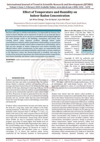
Humidity Effect on the RPC Changguo Lu Princeton University 10/1/2007. Humidity, good or bad to the RPC?.

E N D
Humidity Effect on the RPC Changguo Lu Princeton University 10/1/2007
Humidity, good or bad to the RPC? There are two breeds of RPC: Glass and Bakelite. Their respond to water vapor is very different. There is a common argument, which states that water vapor is bad for the gas chamber, though in fact the water vapor is not always bad for the gas chamber such as adding it into the drift chamber can prevent (or mitigate) the Malter effect. In BaBar drift chamber the 4000ppm water vapor is an essential ingredient of the gas mix, w/o the water vapor serious Malter effect would bring certain part of the chamber into high current self-sustaining mode and ruin the entire chamber. For RPC the same statement is true: water vapor is very bad for glass RPC, but is essential for Bakelite RPC.
In dry gas mix glass RPC performs well The dark current drops, and the efficiency increases while the chamber was drying out.
Bakelite RPC Water vapor plays very different role in the Bakelite RPC. BaBar new version of the endcap RPC has suffered efficient loss due to drying out of the Bakelite. They found that the gas inlet regions of the RPC show lower efficiency. They tested the R.H. at the gas inlet and outlet, the former is almost 0%, but the later is ~ 20 – 30%. That is clear indication of dry gas mixture carrying the water vapor out of RPC. Without beam these low efficient regions show good efficiency, that means actually these regions lost rate capability due to higher resistivity, which is a typical symptom of Bakelite electrode being too dry. After adding water vapor into the gas mix (30% R.H.) these bad regions disappeared. See next slide for comparison [Performance and aging studies of BaBar RPC, Nucl. Phys. B (Proc. Suppl.) 158(2006)139].
Conducting mechanism of glass and Bakleite Glass and Bakelite are insulator material with very high resistivity. Instead of the electron as the charge carrier, in these materials the ions are the charge carriers. The current is ionic current. Not like the metal conducting the current, in which the in and out electrons are always equalized, without replenishment the ion source in the insulator can be run out eventually.
(J.Va’vra, http://www.slac.stanford.edu/~jjv/activity/babar_rpc_my_summary.pdf & “Physics and Chemistry of Aging – Early Developments”, DESY Aging Workshop, 2000). Glass and Bakelite ionic conducting model Vavra’s Bakelite ionic model - A bottom line of this particular model is that if you remove water, the current will stop. Many tests are basically consistent with this point. - The water can be “removed” either by a high current operation or by drying the outer Bakelite layer in a relatively dry gas.
… Glass and Bakelite ionic conducting model The conductivity in standard glasses is attributed to the movement of the alkaline ions, ionic conducting glasses. Typical resistance of these materials is 1012 - 1016Ωcm. However, during the long-term operation, the alkali ions migrate towards the cathode by the electric field and leave a depleted layer close to anode. This leads to a large and permanent increase of the surface resistance.
Humidity effect on surface resistivity (C. Lu 2/24/2002) Bakelite can absorb significant amount of water (more than 0.6% of its own weight). **using linear extrapolation from 0% and 100% data derived this number
Humidity effect on the volume resistivity **using linear extrapolation from 0% and 100% data derived this number
Relative surface resistivity (value @ 100% R.H. as 1) Relative volume resistivity (value @ 100% R.H. as 1) Both surface and volume resistivity are having same trend: resistivity decreases when R.H. increases. For the efficiency important thing is the ratio of , so Bakelite RPC shouldn’t be very sensitive to the atmospheric humidity. Dark current should be affected by R.H. But the inner surface could attach more water molecules under the high electric field, therefore / will decrease loss of efficiency.
Permeability of Polyolefin tubing Dan Marlow and Kazuo Abe did a test on Oct. 1999 to check the permeability of the Polyolefin tubing, which was used for Belle RPC gas distribution. Typically, they were able to achieve a relative humidity of 15% in the dry/wet box. Once the system had fully dried, the nitrogen flow was stopped and the bottom of the box was filled with a small puddle of water. This caused the humidity in the box to quickly (in about 1 hour) climb to 90%.
… Permeability of Polyolefin tubing Permeability of polyethylene is P = 4.6x10⁻¹⁰ g/cm·atm·s. The rate of water vapor penetration is given by dM/dt = Px(∆p·A/s), where s is the thickness of the barrier in cm, A is its area in cm2, and ∆p is the partial pressure diference in atmospheres. ¼” Polyolefin tubing: ID 4.7 mm, OD 6.5 mm, wall thickness 0.89 mm. Then we can derive the simple formula that for the polyolefin tubing the level of water vapor in parts per million Q will be approximately Q = 2080 l*R / F (ppm) , where l is the length of the tube in meters, F is the flow in cc/min, and R is the relative humidity (@50% R.H. R = 0.50). Thus for the 4.5 m length of polyolen at 90% humidity, we expect a water concentration of 842 ppm, in good agreement with the observed value of 940 ppm.
… Permeability of Polyolefin tubing J. Vavra did a similar test, his results are somewhat lower than Belle’s number (same reference as on slide #11) • How much water permeates through a wall • of the 80ft-long 1/4 inch dia. Polyflow tubing ? • - 80ft-long black Polyflow tubing (1/4 inch dia.) • - Keep the tubing at constant temperature of ~ 23oC. • Gas flow ~ 65cc/min; He measured for 80ft ¼” Polyolefin tubing at 85% R.H. under 65 sccm flow rate, the water content at the end would be ~ 325ppm. With the formula on the previous page it would be ~700ppm. For 10m long tubing the number should be 125ppm and 270ppm, respectively.
Teflon tubing permeates much less water vapor • - Switch to BaBar Teflon tubing @ 65cc/min, 61-74% rel. humidity and 93ft long tubing: • - After ~8 hours get only ~200 ppm at 74% humidity. • - After ~16 hours get only ~120 ppm at 71% humidity. • - After ~5 days get only ~30 ppm at 61% humidity !!!!! • - The gas flowing into the BaBar RPCs is rather dry !!!
To study the behavior of RPC system in the possible high humidity environment at the Daya Bay underground experimental hall, we deploy an ad hoc environmental chamber - Thermotron SM4S, which can control the relative humidity and temperature of the chamber. Humidity influence on the dark current
Environmental chamber (2) (4) (1) (5) (3) (1) Thermotron SM4S humidity/temperature; (2) Trigger telescope; (3) Test RPCs inside of the chamber; (4) HP multimeter to monitor HV current; (5) LabView to record/display the HV currents and humidity. (2)
IHEP RPC Test Chambers So far two 50 x 50 cm2 IHEP test RPCs are under the test. Both RPCs were at 40% R.H. for some days. The arrows on the plots show the initial dark current @5800V and 40% R.H. Then we raise R.H. to 90%. The transition was quite slow. RPC #2 dark current was increased more than 35 times from 40% to 90%! The test chamber is only 50 x 50 cm2, if we assume the dark current is due to the leakage along the edges, for a 1m x 2m RPC the edge length will be 3 times of the test chamber, that means @90% R.H. and 5800V the dark current could be 35 x 3 = 105µA!